Toyota Yaris: Can Communication System / Lost Communication With Brake System Control Module(ch2) Missing Message (U117087)
DESCRIPTION
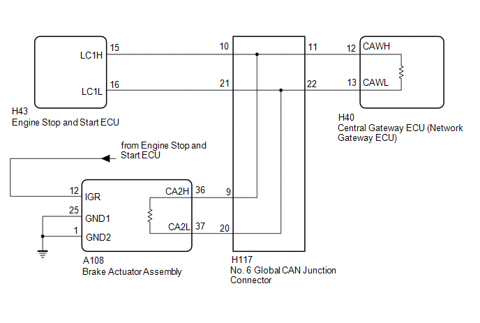
The brake actuator assembly communicates with the ECM and engine stop and start ECU. When the brake actuator assembly does not receive data from the engine stop and start ECU, the engine stop and start ECU stores DTC U117087.
| DTC No. | Detection Item | DTC Detection Condition | Trouble Area | DTC Output from |
|---|---|---|---|---|
| U117087 | Lost Communication With Brake System Control Module(ch2) Missing Message | No communication from the brake actuator assembly continues. |
| Stop and Start |
WIRING DIAGRAM
CAUTION / NOTICE / HINT
CAUTION:
When performing the confirmation driving pattern, obey all speed limits and traffic laws.
NOTICE:
-
Because the order of diagnosis is important to allow correct diagnosis, make sure to begin troubleshooting using How to Proceed with Troubleshooting when CAN communication system related DTCs are output.
Click here

- Before measuring the resistance of the CAN bus, turn the ignition switch off and leave the vehicle for 1 minute or more without operating the key or any switches, or opening or closing the doors. After that, disconnect the cable from the negative (-) auxiliary battery terminal and leave the vehicle for 1 minute or more before measuring the resistance.
-
After the ignition switch is turned off, there may be a waiting time before disconnecting the negative (-) auxiliary battery terminal.
Click here

-
When disconnecting and reconnecting the auxiliary battery, there is an automatic learning function that completes learning when the respective system is used.
Click here

-
Some parts must be initialized and set when replacing or removing and installing parts.
Click here

-
After performing repairs, perform the DTC check procedure and confirm that the DTCs are not output again.
DTC check procedure: Turn the ignition switch to ON and wait for 1 minute or more.
Then operate the suspected malfunctioning system and drive the vehicle at 60 km/h (37 mph) or more for 5 minutes or more.
-
After the repair, perform the CAN bus check and check that all the ECUs and sensors connected to the CAN communication system are displayed as normal.
Click here

HINT:
- Before disconnecting related connectors for inspection, push in on each connector body to check that the connector is not loose or disconnected.
- When a connector is disconnected, check that the terminals and connector body are not cracked, deformed or corroded.
PROCEDURE
| 1. | CHECK FOR CAN BUS BRANCH WIRE |
(a) Turn the ignition switch off.
(b) Disconnect the cable from the negative (-) auxiliary battery terminal.
(c) Measure the resistance according to the value(s) in the table below.

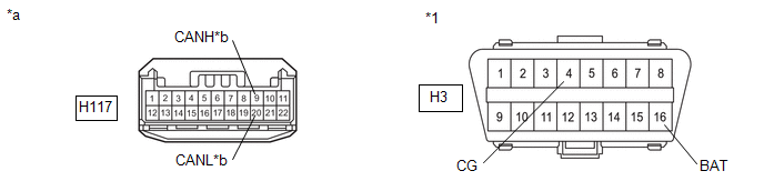
| *1 | DLC3 | - | - |
| *a | Front view of wire harness connector (to No. 6 Global CAN Junction Connector) | *b | to Engine Stop and Start ECU |
Standard Resistance:
| Tester Connection | Condition | Specified Condition | Result |
|---|---|---|---|
| H117-10 (CANH) - H117-21 (CANL) | Cable disconnected from negative (-) auxiliary battery terminal | 54 to 69 Ω | Below 54 Ω: Short circuit between bus lines |
| 70 Ω or more: Open circuit in main bus lines | |||
| H117-10 (CANH) - H3-4 (CG) | Cable disconnected from negative (-) auxiliary battery terminal | 200 Ω or higher | Below 200 Ω: CANH short to ground |
| H117-21 (CANL) - H3-4 (CG) | Cable disconnected from negative (-) auxiliary battery terminal | 200 Ω or higher | Below 200 Ω: CANL short to ground |
| H117-10 (CANH) - H3-16 (BAT) | Cable disconnected from negative (-) auxiliary battery terminal | 6 kΩ or higher | Below 6 kΩ: CANH +B short |
| H117-21 (CANL) - H3-16 (BAT) | Cable disconnected from negative (-) auxiliary battery terminal | 6 kΩ or higher | Below 6 kΩ: CANL +B short |
| Result | Proceed to |
|---|---|
| OK | A |
| NG (Open circuit in CAN main bus lines) | B |
| NG (Short circuit between bus lines) | C |
| NG (+B short or Short to ground) | D |
| B |
 | GO TO STEP 4 |
| C |
 | GO TO STEP 10 |
| D |
 | GO TO STEP 16 |
|

| 2. | CLEAR DTC |
(a) Clear the DTCs.
Powertrain > Stop and Start > Clear DTCs
|

| 3. | CHECK FOR DTC |
(a) Check for DTCs.
Powertrain > Stop and Start > Trouble Codes| Result | Proceed to |
|---|---|
| DTC U117087 is output | A |
| DTC U117087 is not output | B |
| A |
 | REPLACE ENGINE STOP AND START ECU |
| B |
 | USE SIMULATION METHOD TO CHECK |
| 4. | CHECK FOR OPEN IN CAN BUS WIRE (BRAKE ACTUATOR ASSEMBLY MAIN BUS) |
(a) Disconnect the No. 6 global CAN junction connector.
(b) Measure the resistance according to the value(s) in the table below.

| *1 | DLC3 | - | - |
| *a | Front view of wire harness connector (to No. 6 Global CAN Junction Connector) | *b | to Brake Actuator Assembly |
Standard Resistance:
| Tester Connection | Condition | Specified Condition |
|---|---|---|
| H117-9 (CANH) - H117-20 (CANL) | Cable disconnected from negative (-) auxiliary battery terminal | 108 to 132 Ω |
| NG |
 | GO TO STEP 7 |
|

| 5. | CHECK FOR OPEN IN CAN BUS WIRE (CENTRAL GATEWAY ECU (NETWORK GATEWAY ECU) MAIN BUS) |
(a) Disconnect the No. 6 global CAN junction connector.
(b) Measure the resistance according to the value(s) in the table below.

| *1 | DLC3 | - | - |
| *a | Front view of wire harness connector (to No. 6 Global CAN Junction Connector) | *b | to Central Gateway ECU (Network Gateway ECU) |
Standard Resistance:
| Tester Connection | Condition | Specified Condition |
|---|---|---|
| H117-11 (CANH) - H117-22 (CANL) | Cable disconnected from negative (-) auxiliary battery terminal | 108 to 132 Ω |
| NG |
 | GO TO STEP 8 |
|

| 6. | CHECK FOR OPEN IN CAN BUS WIRE (ENGINE STOP AND START ECU BRANCH BUS) |
(a) Disconnect the No. 6 global CAN junction connector.
(b) Measure the resistance according to the value(s) in the table below.

| *1 | DLC3 | - | - |
| *a | Front view of wire harness connector (to No. 6 Global CAN Junction Connector) | *b | to Engine Stop and Start ECU |
Standard Resistance:
| Tester Connection | Condition | Specified Condition |
|---|---|---|
| H117-10 (CANH) - H117-21 (CANL) | Cable disconnected from negative (-) auxiliary battery terminal | 54 to 69 Ω |
| OK |
 | REPLACE NO. 6 GLOBAL CAN JUNCTION CONNECTOR |
| NG |
 | GO TO STEP 9 |
| 7. | CHECK FOR OPEN IN CAN BUS MAIN WIRE (BRAKE ACTUATOR ASSEMBLY) |
(a) Reconnect the H117 No. 6 global CAN junction connector.
(b) Disconnect the brake actuator assembly connector.
| (c) Measure the resistance according to the value(s) in the table below. Standard Resistance:
|
|
| OK |
 | REPLACE BRAKE ACTUATOR ASSEMBLY |
| NG |
 | REPAIR OR REPLACE CAN BUS MAIN WIRE (BRAKE ACTUATOR ASSEMBLY - NO. 6 GLOBAL CAN JUNCTION CONNECTOR) |
| 8. | CHECK FOR OPEN IN CAN BUS MAIN WIRE (CENTRAL GATEWAY ECU (NETWORK GATEWAY ECU)) |
(a) Reconnect the H117 No. 6 global CAN junction connector.
(b) Disconnect the central gateway ECU (network gateway ECU) connector.
| (c) Measure the resistance according to the value(s) in the table below. Standard Resistance:
|
|

| OK |
 | REPLACE CENTRAL GATEWAY ECU (NETWORK GATEWAY ECU) |
| NG |
 | REPAIR OR REPLACE CAN BUS MAIN WIRE (CENTRAL GATEWAY ECU (NETWORK GATEWAY ECU) - NO. 6 GLOBAL CAN JUNCTION CONNECTOR) |
| 9. | CHECK FOR OPEN IN CAN BUS BRANCH WIRE (ENGINE STOP AND START ECU) |
(a) Reconnect the H117 No. 6 global CAN junction connector.
(b) Disconnect the engine stop and start ECU connector.
| (c) Measure the resistance according to the value(s) in the table below. Standard Resistance:
|
|

| OK |
 | REPLACE ENGINE STOP AND START ECU |
| NG |
 | REPAIR OR REPLACE CAN BUS BRANCH WIRE (ENGINE STOP AND START ECU - NO. 6 GLOBAL CAN JUNCTION CONNECTOR) |
| 10. | CHECK FOR SHORT IN CAN BUS WIRES (BRAKE ACTUATOR ASSEMBLY MAIN BUS) |
(a) Disconnect the No. 6 global CAN junction connector.
(b) Measure the resistance according to the value(s) in the table below.

| *1 | DLC3 | - | - |
| *a | Front view of wire harness connector (to No. 6 Global CAN Junction Connector) | *b | to Brake Actuator Assembly |
Standard Resistance:
| Tester Connection | Condition | Specified Condition |
|---|---|---|
| H117-9 (CANH) - H117-20 (CANL) | Cable disconnected from negative (-) auxiliary battery terminal | 108 to 132 Ω |
| NG |
 | GO TO STEP 13 |
|

| 11. | CHECK FOR SHORT IN CAN BUS WIRES (CENTRAL GATEWAY ECU (NETWORK GATEWAY ECU) MAIN BUS) |
(a) Disconnect the No. 6 global CAN junction connector.
(b) Measure the resistance according to the value(s) in the table below.

| *1 | DLC3 | - | - |
| *a | Front view of wire harness connector (to No. 6 Global CAN Junction Connector) | *b | to Central Gateway ECU (Network Gateway ECU) |
Standard Resistance:
| Tester Connection | Condition | Specified Condition |
|---|---|---|
| H117-11 (CANH) - H117-22 (CANL) | Cable disconnected from negative (-) auxiliary battery terminal | 108 to 132 Ω |
| NG |
 | GO TO STEP 14 |
|

| 12. | CHECK FOR SHORT IN CAN BUS WIRES (ENGINE STOP AND START ECU BRANCH BUS) |
(a) Disconnect the No. 6 global CAN junction connector.
(b) Measure the resistance according to the value(s) in the table below.

| *1 | DLC3 | - | - |
| *a | Front view of wire harness connector (to No. 6 Global CAN Junction Connector) | *b | to Engine Stop and Start ECU |
Standard Resistance:
| Tester Connection | Condition | Specified Condition |
|---|---|---|
| H117-10 (CANH) - H117-21 (CANL) | Cable disconnected from negative (-) auxiliary battery terminal | 54 to 69 Ω |
| OK |
 | REPLACE NO. 6 GLOBAL CAN JUNCTION CONNECTOR |
| NG |
 | GO TO STEP 15 |
| 13. | CHECK FOR SHORT IN CAN BUS WIRES (BRAKE ACTUATOR ASSEMBLY) |
(a) Reconnect the H117 No. 6 global CAN junction connector.
(b) Disconnect the brake actuator assembly connector.
| (c) Measure the resistance according to the value(s) in the table below. Standard Resistance:
|
|

| OK |
 | REPLACE BRAKE ACTUATOR ASSEMBLY |
| NG |
 | REPAIR OR REPLACE CAN BUS MAIN WIRE (BRAKE ACTUATOR ASSEMBLY - NO. 6 GLOBAL CAN JUNCTION CONNECTOR) |
| 14. | CHECK FOR OPEN IN CAN BUS MAIN WIRE (CENTRAL GATEWAY ECU (NETWORK GATEWAY ECU)) |
(a) Reconnect the H117 No. 6 global CAN junction connector.
(b) Disconnect the central gateway ECU (network gateway ECU) connector.
| (c) Measure the resistance according to the value(s) in the table below. Standard Resistance:
|
|
| OK |
 | REPLACE CENTRAL GATEWAY ECU (NETWORK GATEWAY ECU) |
| NG |
 | REPAIR OR REPLACE CAN BUS MAIN WIRE (CENTRAL GATEWAY ECU (NETWORK GATEWAY ECU) - NO. 6 GLOBAL CAN JUNCTION CONNECTOR) |
| 15. | CHECK FOR SHORT IN CAN BUS WIRES (ENGINE STOP AND START ECU) |
(a) Reconnect the H117 No. 6 global CAN junction connector.
(b) Disconnect the engine stop and start ECU connector.
| (c) Measure the resistance according to the value(s) in the table below. Standard Resistance:
|
|
| OK |
 | REPLACE ENGINE STOP AND START ECU |
| NG |
 | REPAIR OR REPLACE CAN BUS BRANCH WIRE (ENGINE STOP AND START ECU - NO. 6 GLOBAL CAN JUNCTION CONNECTOR) |
| 16. | CHECK FOR SHORT IN CAN BUS WIRES (BRAKE ACTUATOR ASSEMBLY MAIN BUS) |
(a) Disconnect the No. 6 global CAN junction connector.
(b) Measure the resistance according to the value(s) in the table below.
| *1 | DLC3 | - | - |
| *a | Front view of wire harness connector (to No. 6 Global CAN Junction Connector) | *b | to Brake Actuator Assembly |
Standard Resistance:
| Tester Connection | Condition | Specified Condition |
|---|---|---|
| H117-9 (CANH) - H3-4 (CG) | Cable disconnected from negative (-) auxiliary battery terminal | 200 Ω or higher |
| H117-20 (CANL) - H3-4 (CG) | Cable disconnected from negative (-) auxiliary battery terminal | 200 Ω or higher |
| H117-9 (CANH) - H3-16 (BAT) | Cable disconnected from negative (-) auxiliary battery terminal | 6 kΩ or higher |
| H117-20 (CANL) - H3-16 (BAT) | Cable disconnected from negative (-) auxiliary battery terminal | 6 kΩ or higher |
| NG |
 | GO TO STEP 19 |
|

| 17. | CHECK FOR SHORT IN CAN BUS WIRES (CENTRAL GATEWAY ECU (NETWORK GATEWAY ECU) MAIN BUS) |
(a) Disconnect the No. 6 global CAN junction connector.
(b) Measure the resistance according to the value(s) in the table below.

| *1 | DLC3 | - | - |
| *a | Front view of wire harness connector (to No. 6 Global CAN Junction Connector) | *b | to Central Gateway ECU (Network Gateway ECU) |
Standard Resistance:
| Tester Connection | Condition | Specified Condition |
|---|---|---|
| H117-11 (CANH) - H3-4 (CG) | Cable disconnected from negative (-) auxiliary battery terminal | 200 Ω or higher |
| H117-22 (CANL) - H3-4 (CG) | Cable disconnected from negative (-) auxiliary battery terminal | 200 Ω or higher |
| H117-11 (CANH) - H3-16 (BAT) | Cable disconnected from negative (-) auxiliary battery terminal | 6 kΩ or higher |
| H117-22 (CANL) - H3-16 (BAT) | Cable disconnected from negative (-) auxiliary battery terminal | 6 kΩ or higher |
| NG |
 | GO TO STEP 20 |
|

| 18. | CHECK FOR SHORT IN CAN BUS WIRES (ENGINE STOP AND START ECU BRANCH BUS) |
(a) Disconnect the No. 6 global CAN junction connector.
(b) Measure the resistance according to the value(s) in the table below.

| *1 | DLC3 | - | - |
| *a | Front view of wire harness connector (to No. 6 Global CAN Junction Connector) | *b | to Engine Stop and Start ECU |
Standard Resistance:
| Tester Connection | Condition | Specified Condition |
|---|---|---|
| H117-10 (CANH) - H3-4 (CG) | Cable disconnected from negative (-) auxiliary battery terminal | 200 Ω or higher |
| H117-21 (CANL) - H3-4 (CG) | Cable disconnected from negative (-) auxiliary battery terminal | 200 Ω or higher |
| H117-10 (CANH) - H3-16 (BAT) | Cable disconnected from negative (-) auxiliary battery terminal | 6 kΩ or higher |
| H117-21 (CANL) - H3-16 (BAT) | Cable disconnected from negative (-) auxiliary battery terminal | 6 kΩ or higher |
| OK |
 | REPLACE NO. 6 GLOBAL CAN JUNCTION CONNECTOR |
| NG |
 | GO TO STEP 21 |
| 19. | CHECK FOR SHORT IN CAN BUS WIRES (BRAKE ACTUATOR ASSEMBLY) |
(a) Reconnect the H117 No. 6 global CAN junction connector.
(b) Disconnect the brake actuator assembly connector.
(c) Measure the resistance according to the value(s) in the table below.
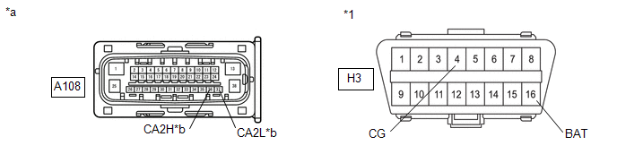
| *1 | DLC3 | - | - |
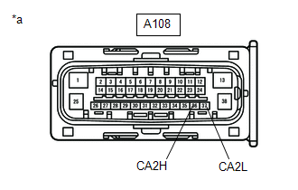
| *a | Front view of wire harness connector (to Brake Actuator Assembly) | *b | to No. 6 Global CAN Junction Connector |
Standard Resistance:
| Tester Connection | Condition | Specified Condition |
|---|---|---|
| A108-36 (CA2H) - H3-4 (CG) | Cable disconnected from negative (-) auxiliary battery terminal | 200 Ω or higher |
| A108-37 (CA2L) - H3-4 (CG) | Cable disconnected from negative (-) auxiliary battery terminal | 200 Ω or higher |
| A108-36 (CA2H) - H3-16 (BAT) | Cable disconnected from negative (-) auxiliary battery terminal | 6 kΩ or higher |
| A108-37 (CA2L) - H3-16 (BAT) | Cable disconnected from negative (-) auxiliary battery terminal | 6 kΩ or higher |
| OK |
 | REPLACE BRAKE ACTUATOR ASSEMBLY |
| NG |
 | REPAIR OR REPLACE CAN BUS MAIN WIRE (BRAKE ACTUATOR ASSEMBLY - NO. 6 GLOBAL CAN JUNCTION CONNECTOR) |
| 20. | CHECK FOR OPEN IN CAN BUS MAIN WIRE (CENTRAL GATEWAY ECU (NETWORK GATEWAY ECU)) |
(a) Reconnect the H117 No. 6 global CAN junction connector.
(b) Disconnect the central gateway ECU (network gateway ECU) connector.
(c) Measure the resistance according to the value(s) in the table below.
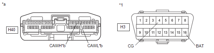
| *1 | DLC3 | - | - |
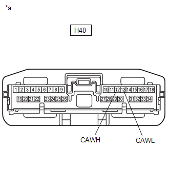
| *a | Front view of wire harness connector (to Central Gateway ECU (Network Gateway ECU)) | *b | to No. 6 Global CAN Junction Connector |
Standard Resistance:
| Tester Connection | Condition | Specified Condition |
|---|---|---|
| H40-12 (CAWH) - H3-4 (CG) | Cable disconnected from negative (-) auxiliary battery terminal | 200 Ω or higher |
| H40-13 (CAWL) - H3-4 (CG) | Cable disconnected from negative (-) auxiliary battery terminal | 200 Ω or higher |
| H40-12 (CAWH) - H3-16 (BAT) | Cable disconnected from negative (-) auxiliary battery terminal | 6 kΩ or higher |
| H40-13 (CAWL) - H3-16 (BAT) | Cable disconnected from negative (-) auxiliary battery terminal | 6 kΩ or higher |
| OK |
 | REPLACE CENTRAL GATEWAY ECU (NETWORK GATEWAY ECU) |
| NG |
 | REPAIR OR REPLACE CAN BUS MAIN WIRE (CENTRAL GATEWAY ECU (NETWORK GATEWAY ECU) - NO. 6 GLOBAL CAN JUNCTION CONNECTOR) |
| 21. | CHECK FOR SHORT IN CAN BUS WIRES (ENGINE STOP AND START ECU) |
(a) Reconnect the H117 No. 6 global CAN junction connector.
(b) Disconnect the engine stop and start ECU connector.
(c) Measure the resistance according to the value(s) in the table below.
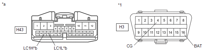
| *1 | DLC3 | - | - |
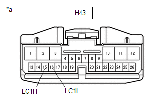
| *a | Front view of wire harness connector (to Engine Stop and Start ECU) | *b | to No. 6 Global CAN Junction Connector |
Standard Resistance:
| Tester Connection | Condition | Specified Condition |
|---|---|---|
| H43-15 (LC1H) - H3-4 (CG) | Cable disconnected from negative (-) auxiliary battery terminal | 200 Ω or higher |
| H43-16 (LC1L) - H3-4 (CG) | Cable disconnected from negative (-) auxiliary battery terminal | 200 Ω or higher |
| H43-15 (LC1H) - H3-16 (BAT) | Cable disconnected from negative (-) auxiliary battery terminal | 6 kΩ or higher |
| H43-16 (LC1L) - H3-16 (BAT) | Cable disconnected from negative (-) auxiliary battery terminal | 6 kΩ or higher |
| OK |
 | REPLACE ENGINE STOP AND START ECU |
| NG |
 | REPAIR OR REPLACE CAN BUS BRANCH WIRE (ENGINE STOP AND START ECU - NO. 6 GLOBAL CAN JUNCTION CONNECTOR) |
 Central Gateway ECU System Internal Failure (B102004)
DESCRIPTION DTC No. Detection Item DTC Detection Condition Trouble Area DTC Output from B102004 Central Gateway ECU System Internal Failure A malfunction in the non-volatile storage of the central gateway ECU (network gateway ECU) is detected...
 Check CAN Communication Connection
DESCRIPTION Symptom Trouble Area Check CAN Communication Connection
CAN main bus line, CAN branch line or connector
Power source circuit of central gateway ECU (network gateway ECU)
Central gateway ECU (network gateway ECU) ground circuit
Central gateway ECU (network gateway ECU)
Power source circuit of DLC3
DLC3 ground circuit
WIRING DIAGRAM
CAUTION / NOTICE / HINT CAUTION: When performing the confirmation driving pattern, obey all speed limits and traffic laws...
Other information:
Toyota Yaris XP210 (2020-2026) Owner's Manual: Parking Brake
Setting the parking brake Depress the brake pedal and then firmly pull the parking brake lever fully upwards with sufficient force to hold the vehicle in a stationary position. Releasing the parking brake Depress the brake pedal and pull the parking brake lever upwards, then press the release button...
Toyota Yaris XP210 (2020-2026) Reapir and Service Manual: Brake
BRAKE INSPECT BRAKE LINE PIPES AND HOSES HINT: Work in a well-lighted area. Turn the front wheels fully to the right or left before beginning the inspection. (a) Using a mirror, check the entire circumference and length of the brake lines and hoses for: Damage Wear Deformation Cracks Kinks Corrosion Leaks Twists (b) Check all the clamps for tightness and check the connections for leakage...
Categories
- Manuals Home
- Toyota Yaris Owners Manual
- Toyota Yaris Service Manual
- How to connect USB port/Auxiliary jack
- Power Integration No.1 System Missing Message (B235287,B235587,B235787-B235987)
- To Set Speed
- New on site
- Most important about car
Turning the Engine Off
Stop the vehicle completely. Manual transaxle: Shift into neutral and set the parking brake.Automatic transaxle: Shift the selector lever to the P position and set the parking brake.
Press the push button start to turn off the engine. The ignition position is off.