Toyota Yaris: Front Bumper / Installation
INSTALLATION
PROCEDURE
1. INSTALL FRONT BUMPER ASSEMBLY
(a) Install the 3 grommets.
HINT:
Use the same procedure for the RH side and LH side.
(b) Temporarily install the front bumper assembly with the 2 clips and 2 bolts.
(c) w/ Pre-collision System:
(1) Connect the connector.
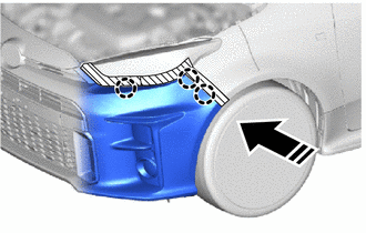
(d) Pull back the side of the front bumper assembly.
.png)
NOTICE:
Do not apply excessive force when pulling back the front bumper assembly.
(e) Connect the 2 connectors.
(f) Engage the claws to install the front bumper assembly as shown in the illustration.
HINT:
Use the same procedure for the RH side and LH side.
.png) | Install in this Direction |
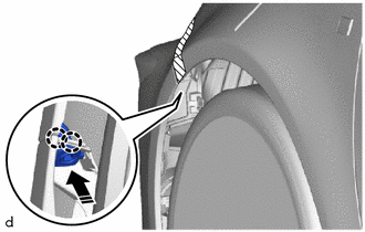
(g) Engage the claws to install the bracket as shown in the illustration.
|
| Install in this Direction |
HINT:
Use the same procedure for the RH side and LH side.
(h) Install the screw.
HINT:
Use the same procedure for the RH side and LH side.
(i) Install the 10 screws.
2. INSTALL PIN HOLD CLIP
(a) Engage the claws to install the 2 pin hold clips.
HINT:
Use the same procedure for the RH side and LH side.
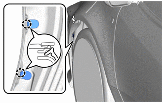
.png) | Protective Tape |
(b) Remove the protective tape.
3. ADJUST HEADLIGHT AIMING
Click here
.gif)
4. ADJUST FOG LIGHT AIMING
Click here
5. ADJUST MILLIMETER WAVE RADAR SENSOR (w/ Pre-collision System)
(a) When the millimeter wave radar sensor assembly is replaced with a new one, adjustment of the radar sensor beam axis must be performed.
HINT:
Millimeter wave radar sensor assembly Learning can be performed by using either Triangle Target or Flat Surface Target or Driving Adjustment.
-
Triangle Target:
Click here
-
Flat Surface Target:
Click here
-
Driving Adjustment:
Click here
 Reassembly
REASSEMBLY PROCEDURE 1. INSTALL FRONT BUMPER LOWER ABSORBER (a) Install the 4 grommets.
(b) Engage the claws to install the front bumper lower absorber...

Other information:
Toyota Yaris XP210 (2020-2026) Reapir and Service Manual: Removal
REMOVAL PROCEDURE 1. SEPARATE ENGINE WIRE (a) Remove the bolt and engine wire. 2. REMOVE IGNITION COIL ASSEMBLY (a) Disconnect the ignition coil assembly connector. (b) Remove the bolt and ignition coil assembly. 3. REMOVE CAMSHAFT POSITION SENSOR (for Intake Side) (a) Disconnect the camshaft position sensor connector...
Toyota Yaris XP210 (2020-2026) Reapir and Service Manual: Disposal
DISPOSAL CAUTION / NOTICE / HINT CAUTION: Before performing pre-disposal deployment of any SRS part, review and closely follow all applicable environmental and hazardous material regulations. Pre-disposal deployment may be considered hazardous material treatment...
Categories
- Manuals Home
- Toyota Yaris Owners Manual
- Toyota Yaris Service Manual
- Auto Lock/Unlock Function
- G16e-gts (engine Mechanical)
- Fuel Gauge
- New on site
- Most important about car
Fuel-Filler Lid and Cap
WARNING
When removing the fuel-filler cap, loosen the cap slightly and wait for any hissing to stop, then remove it
Fuel spray is dangerous. Fuel can burn skin and eyes and cause illness if ingested. Fuel spray is released when there is pressure in the fuel tank and the fuel-filler cap is removed too quickly.