
Toyota Yaris: Exterior Panels / Trim / Front Door Belt Moulding
Toyota Yaris XP210 (2020-2026) Reapir and Service Manual / Vehicle Exterior / Exterior Panels / Trim / Front Door Belt Moulding
 Installation
INSTALLATION PROCEDURE 1. INSTALL FRONT BUMPER ASSEMBLY (a) Install the 3 grommets. HINT: Use the same procedure for the RH side and LH side. (b) Temporarily install the front bumper assembly with the 2 clips and 2 bolts...
 Components
COMPONENTS ILLUSTRATION
*1 FRONT DOOR GLASS SUB-ASSEMBLY *2 FRONT DOOR SERVICE HOLE COVER *3 FRONT DOOR GLASS OUTER WEATHERSTRIP ASSEMBLY *4 HOLE PLUG *5 WINDOW REGULATOR SHIM - -
N*m (kgf*cm, ft...
Other information:
Toyota Yaris XP210 (2020-2026) Owner's Manual: Immobilizer System
The immobilizer system allows the engine to start only with a key the system recognizes. If someone attempts to start the engine with an unrecognized key, the engine will not start, thereby helping to prevent vehicle theft. If you have a problem with the immobilizer system or the key, consult your Toyota dealer...
Toyota Yaris XP210 (2020-2026) Reapir and Service Manual: On-vehicle Inspection
ON-VEHICLE INSPECTION CAUTION / NOTICE / HINT The necessary procedures (adjustment, calibration, initialization or registration) that must be performed after parts are removed and installed, or replaced when repairing air leaks in the intake system are shown below...
Categories
- Manuals Home
- Toyota Yaris Owners Manual
- Toyota Yaris Service Manual
- Fuse Panel Description
- Immobilizer System
- Opening and Closing the Liftgate/Trunk Lid
- New on site
- Most important about car
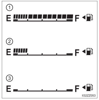
Fuel Gauge
The fuel gauge shows approximately how much fuel is remaining in the tank when the ignition is switched ON. We recommend keeping the tank over 1/4 full.

Copyright © 2026 www.toyaris4.com