
Toyota Yaris: Front Door Belt Moulding / Removal
REMOVAL
CAUTION / NOTICE / HINT
The necessary procedures (adjustment, calibration, initialization or registration) that must be performed after parts are removed and installed, or replaced during the front door belt moulding removal/installation are shown below.
Necessary Procedure After Parts Removed/Installed/Replaced| Replaced Part or Performed Procedure | Necessary Procedure | Effect/Inoperative Function when Necessary Procedure not Performed | Link |
|---|---|---|---|
| Door glass | Initialize power window control system |
|
|
HINT:
-
When the cable is disconnected/reconnected to the auxiliary battery terminal, systems temporarily stop operating. However, each system has a function that completes learning the first time the system is used.
-
Learning completes when vehicle is driven
Effect/Inoperative Function When Necessary Procedures are not Performed
Necessary Procedures
Link
Lane tracing assist system
Drive the vehicle straight ahead at 35 km/h (22 mph) or more for 5 second or more.
.gif)
Pre-collision system
Stop and start system
Drive the vehicle until stop and start control is permitted (approximately 5 to 60 minutes)
-
Learning completes when vehicle is operated normally
Effect/Inoperative Function When Necessary Procedures are not Performed
Necessary Procedures
Link
Power door lock control system
- Back door opener
Perform door unlock operation with door control switch or electrical key transmitter sub-assembly switch.
Air conditioning system
After the ignition switch is turned to ON, the servo motor standard position is recognized.
-
-
Learning completes when vehicle is driven
- Use the same procedure for the RH side and LH side.
- The following procedure is for the LH side.
PROCEDURE
1. PRECAUTION
NOTICE:
After the ignition switch is turned off, there may be a waiting time before disconnecting the negative (-) auxiliary battery terminal.
Click here
2. DISCONNECT CABLE FROM NEGATIVE AUXILIARY BATTERY TERMINAL
Click here
3. REMOVE OUTER REAR VIEW MIRROR ASSEMBLY
Click here
4. REMOVE FRONT DOOR SERVICE HOLE COVER
Click here
5. REMOVE HOLE PLUG
Click here
6. REMOVE WINDOW REGULATOR SHIM
Click here
7. REMOVE FRONT DOOR GLASS SUB-ASSEMBLY
Click here
8. REMOVE FRONT DOOR GLASS OUTER WEATHERSTRIP ASSEMBLY
(a) Apply protective tape around the front door glass outer weatherstrip assembly.
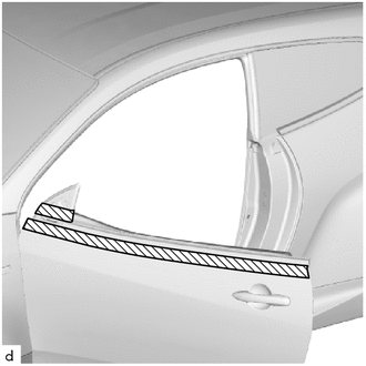
.png) | Protective Tape |
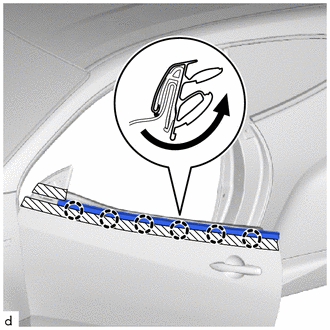
| (b) Disengage the claws to remove the front door glass outer weatherstrip assembly as shown in the illustration. |
|
 Components
COMPONENTS ILLUSTRATION
*1 FRONT DOOR GLASS SUB-ASSEMBLY *2 FRONT DOOR SERVICE HOLE COVER *3 FRONT DOOR GLASS OUTER WEATHERSTRIP ASSEMBLY *4 HOLE PLUG *5 WINDOW REGULATOR SHIM - -
N*m (kgf*cm, ft...
 Installation
INSTALLATION CAUTION / NOTICE / HINT HINT:
Use the same procedure for the RH side and LH side.
The following procedure is for the LH side.
PROCEDURE 1...
Other information:
Toyota Yaris XP210 (2020-2026) Owner's Manual: Bluetooth® Audio
Applicable Bluetooth® specification (Recommended)Ver. 1.1/1.2/2.0 + EDR/2.1 + EDR/3.0 (conformity) Response profile A2DP (Advanced Audio Distribution Profile) Ver. 1.0/1.2 AVRCP (Audio/Video Remote Control Profile) Ver. 1.0/1.3/1.4 A2DP is a profile which transmits only audio to the Bluetooth® unit...
Toyota Yaris XP210 (2020-2026) Reapir and Service Manual: Removal
REMOVAL CAUTION / NOTICE / HINT HINT: When the cable is disconnected / reconnected to the auxiliary battery terminal, systems temporarily stop operating. However, each system has a function that completes learning the first time the system is used. Learning completes when vehicle is driven Effect/Inoperative Function When Necessary Procedures are not Performed Necessary Procedures Link Lane tracing assist system Drive the vehicle straight ahead at 35 km/h (22 mph) or more for 5 second or more...
Categories
- Manuals Home
- Toyota Yaris Owners Manual
- Toyota Yaris Service Manual
- Removal
- G16e-gts (engine Mechanical)
- How to connect USB port/Auxiliary jack
- New on site
- Most important about car
Supplemental Restraint System (SRS) Precautions
The front and side supplemental restraint systems (SRS) include different types of air bags. Please verify the different types of air bags which are equipped on your vehicle by locating the “SRS AIRBAG” location indicators. These indicators are visible in the area where the air bags are installed.
The air bags are installed in the following locations:
The steering wheel hub (driver air bag) The front passenger dashboard (front passenger air bag) The outboard sides of the front seatbacks (side air bags) The front and rear window pillars, and the roof edge along both sides (curtain air bags)