
Toyota Yaris: Stop Light Switch / Removal
REMOVAL
PROCEDURE
1. REMOVE NO. 1 INSTRUMENT PANEL UNDER COVER SUB-ASSEMBLY
Click here
.gif)
2. REMOVE STOP LIGHT SWITCH ASSEMBLY
| (a) Disconnect the connector. |
|
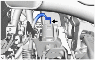
(b) Remove the stop light switch assembly as shown in the illustration.
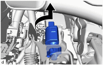
.png) | Remove in this Direction |
3. REMOVE STOP LIGHT SWITCH MOUNTING ADJUSTER
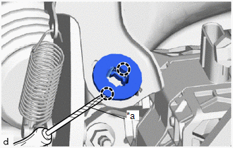
| (a) Using a screwdriver with its tip wrapped with protective tape, disengage the claws to remove the stop light switch mounting adjuster. NOTICE: The stop light switch mounting adjuster must not be reused. |
|
 On-vehicle Inspection
ON-VEHICLE INSPECTION PROCEDURE 1. INSPECT STOP LIGHT SWITCH ASSEMBLY (a) Disconnect the stop light switch assembly connector. (b) Measure the voltage and resistance on the wire harness side connector according to the value(s) in the table below...
 Installation
INSTALLATION PROCEDURE 1. INSTALL STOP LIGHT SWITCH MOUNTING ADJUSTER (a) Engage the claws to install a new stop light switch mounting adjuster.
2...
Other information:
Toyota Yaris XP210 (2020-2026) Reapir and Service Manual: Fail-safe Chart
F..
Toyota Yaris XP210 (2020-2026) Reapir and Service Manual: Removal
REMOVAL CAUTION / NOTICE / HINT The necessary procedures (adjustment, calibration, initialization or registration) that must be performed after parts are removed and installed, or replaced during No. 2 fuel pressure sensor removal/installation are shown below...
Categories
- Manuals Home
- Toyota Yaris Owners Manual
- Toyota Yaris Service Manual
- How to connect USB port/Auxiliary jack
- Battery Monitor Module General Electrical Failure (P058A01)
- Adjustment
- New on site
- Most important about car
Refueling
Before refueling, close all the doors, windows, and the liftgate/trunk lid, and switch the ignition OFF.
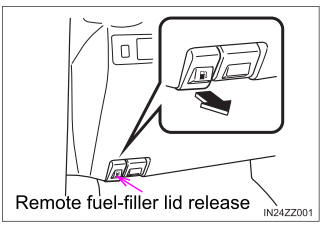
To open the fuel-filler lid, pull the remote fuel-filler lid release.

Copyright © 2026 www.toyaris4.com