Toyota Yaris: Rear Seat Assembly / Disassembly
DISASSEMBLY
CAUTION / NOTICE / HINT
CAUTION:
Wear protective gloves. Sharp areas on the parts may injure your hands.
PROCEDURE
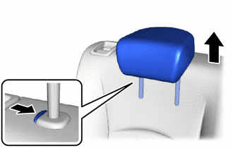
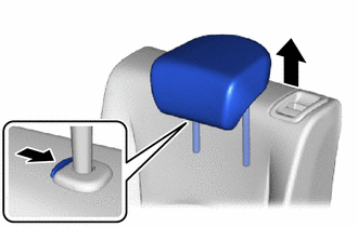
1. REMOVE REAR SEAT HEADREST ASSEMBLY
| (a) Remove the rear seat headrest assembly. |
|
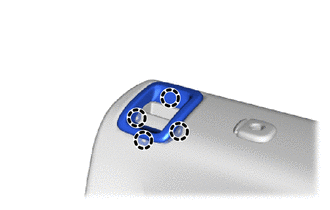
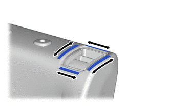
2. REMOVE REAR SEATBACK LOCK UPPER BEZEL
| (a) Disengage the claws to remove the rear seatback lock upper bezel. |
|
| (b) Disengage the hooks from the separate type rear seatback cover RH. |
|
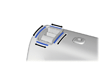
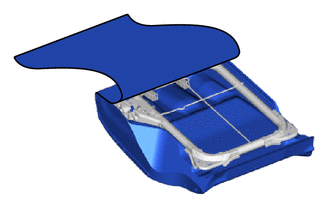
3. REMOVE REAR SEATBACK BOARD SUB-ASSEMBLY RH
| (a) Disengage the hook. |
|
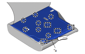
(b) Open the fasteners.
| (c) Using a screwdriver with its tip wrapped in protective tape, disengage the claws and guides to remove the rear seatback board sub-assembly RH. |
|
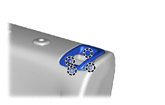
4. REMOVE REAR SEAT HEADREST SUPPORT
| (a) Disengage the claws to remove the 2 rear seat headrest supports. |
|
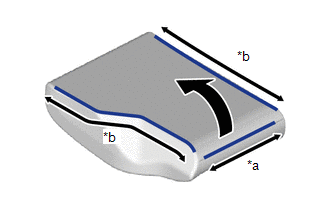
5. REMOVE SEPARATE TYPE REAR SEATBACK COVER WITH PAD RH
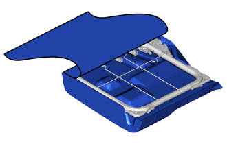
| (a) Remove the separate type rear seatback cover with pad RH from the rear seatback frame sub-assembly RH. |
|
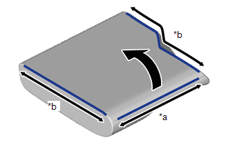
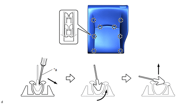
6. REMOVE SEPARATE TYPE REAR SEATBACK COVER RH
(a) Using a screwdriver, disengage the claws to remove the separate type rear seatback cover RH from the separate type rear seatback pad RH as shown in the illustration.
| *a | Screwdriver | - | - |
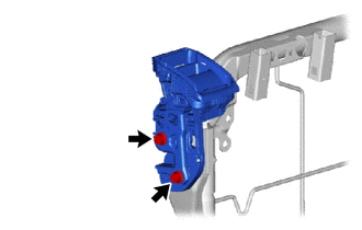
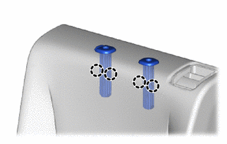
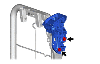
7. REMOVE REAR SEATBACK LOCK ASSEMBLY RH
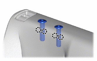
| (a) Remove the 2 bolts and rear seatback lock assembly RH. |
|
8. REMOVE REAR SEAT HEADREST ASSEMBLY
| (a) Remove the rear seat headrest assembly. |
|
9. REMOVE REAR SEATBACK LOCK UPPER BEZEL
| (a) Disengage the claws to remove the rear seatback lock upper bezel. |
|
| (b) Disengage the hooks from the separate type rear seatback cover LH. |
|
10. REMOVE REAR SEATBACK BOARD SUB-ASSEMBLY LH
| (a) Disengage the hook. |
|
(b) Open the fasteners.
| (c) Using a screwdriver with its tip wrapped in protective tape, disengage the claws and guides to remove the rear seatback board sub-assembly LH. |
|
11. REMOVE REAR SEAT HEADREST SUPPORT
| (a) Disengage the claws to remove the 2 rear seat headrest supports. |
|
12. REMOVE SEPARATE TYPE REAR SEATBACK COVER WITH PAD LH
| (a) Remove the separate type rear seatback cover with pad LH from the rear seatback frame sub-assembly LH. |
|
13. REMOVE SEPARATE TYPE REAR SEATBACK COVER LH
(a) Using a screwdriver, disengage the claws to remove the separate type rear seatback cover LH from the separate type rear seatback pad LH as shown in the illustration.
| *a | Screwdriver | - | - |
14. REMOVE REAR SEATBACK LOCK ASSEMBLY LH
| (a) Remove the 2 bolts and rear seatback lock assembly LH. |
|
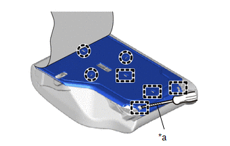
15. REMOVE BENCH TYPE REAR SEAT CUSHION COVER
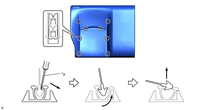
(a) Disengage the hook and loop fasteners and hooks.
(b) Using a screwdriver, disengage the claws to remove the bench type rear seat cushion cover from the rear seat cushion pad sub-assembly as shown in the illustration.
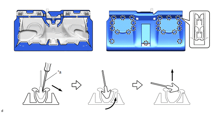
| *a | Screwdriver | - | - |
 | Hook and Loop Fastener | - | - |
 Removal
REMOVAL CAUTION / NOTICE / HINT CAUTION: Wear protective gloves. Sharp areas on the parts may injure your hands. PROCEDURE 1. REMOVE REAR SEATBACK ASSEMBLY RH (a) Fold the rear seatback assembly RH forward...
 Reassembly
REASSEMBLY CAUTION / NOTICE / HINT CAUTION: Wear protective gloves. Sharp areas on the parts may injure your hands. PROCEDURE 1. INSTALL BENCH TYPE REAR SEAT CUSHION COVER NOTICE: When installing a bench type rear seat cushion cover, refer to Precaution in order to prevent wrinkles from forming...
Other information:
Toyota Yaris XP210 (2020-2026) Reapir and Service Manual: Parts Location
PARTS LOCATION ILLUSTRATION *1 HEADLIGHT ASSEMBLY RH - TURN SIGNAL LIGHT *2 SIDE TURN SIGNAL LIGHT ASSEMBLY RH *3 SIDE TURN SIGNAL LIGHT ASSEMBLY LH *4 REAR COMBINATION LIGHT ASSEMBLY RH - TURN SIGNAL LIGHT *5 REAR COMBINATION LIGHT ASSEMBLY LH - TURN SIGNAL LIGHT *6 HEADLIGHT ASSEMBLY LH - TURN SIGNAL LIGHT ILLUSTRATION *1 FRONT DOOR LOCK WITH MOTOR ASSEMBLY RH *2 SMART DOOR CONTROL RECEIVER ASSEMBLY *3 FRONT DOOR COURTESY LIGHT SWITCH ASSEMBLY RH *4 FRONT DOOR COURTESY LIGHT SWITCH ASSEMBLY LH *5 FRONT DOOR LOCK WITH MOTOR ASSEMBLY LH *6 POWER DISTRIBUTION BOX ASSEMBLY - ECU-IGR NO...
Toyota Yaris XP210 (2020-2026) Reapir and Service Manual: Installation
INSTALLATION CAUTION / NOTICE / HINT HINT: Use the same procedure for the RH and LH sides. The procedure listed below is for the LH side. PROCEDURE 1. INSTALL FRONT NO. 1 SPEAKER BRACKET (a) Engage the hooks to install the front No. 1 speaker bracket...
Categories
- Manuals Home
- Toyota Yaris Owners Manual
- Toyota Yaris Service Manual
- Removal
- Fuse Panel Description
- Battery Monitor Module General Electrical Failure (P058A01)
- New on site
- Most important about car
Break-In Period
No special break-in is necessary, but a few precautions in the first 600 miles (1,000 km) may add to the performance, economy, and life of the vehicle.
Do not race the engine. Do not maintain one constant speed, either slow or fast, for a long period of time. Do not drive constantly at full-throttle or high engine rpm for extended periods of time. Avoid unnecessary hard stops. Avoid full-throttle starts.