Toyota Yaris: Stop Light Switch / On-vehicle Inspection
ON-VEHICLE INSPECTION
PROCEDURE
1. INSPECT STOP LIGHT SWITCH ASSEMBLY
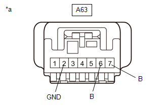
(a) Disconnect the stop light switch assembly connector.
| (b) Measure the voltage and resistance on the wire harness side connector according to the value(s) in the table below. Standard Voltage:
Standard Resistance:
If the result is not as specified, repair or replace the wire harness or connector. |
|
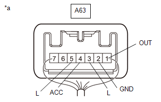
(c) Reconnect the stop light switch assembly connector.
| (d) Measure the voltage according to the value(s) in the table below. Standard Voltage:
If the result is not as specified, replace the stop light switch assembly. |
|
 Components
C..
 Removal
REMOVAL PROCEDURE 1. REMOVE NO. 1 INSTRUMENT PANEL UNDER COVER SUB-ASSEMBLY Click here
2. REMOVE STOP LIGHT SWITCH ASSEMBLY (a) Disconnect the connector...
Other information:
Toyota Yaris XP210 (2020-2026) Owner's Manual: Fog Lights
Use this switch to turn on the fog lights. The fog lights will improve visibility at night and during foggy conditions. The fog lights can be used when the ignition is switched ON. The fog lights turn on when the fog light switch is turned to the position and turn off when the switch is turned to the OFF position...
Toyota Yaris XP210 (2020-2026) Reapir and Service Manual: Lubrication System
On-vehicle InspectionON-VEHICLE INSPECTION PROCEDURE 1. CHECK ENGINE OIL LEVEL (a) Warm up and stop the engine, then wait for 5 minutes. (b) Check that the engine oil level is between the low level and full level marks on the engine oil level dipstick...
Categories
- Manuals Home
- Toyota Yaris Owners Manual
- Toyota Yaris Service Manual
- G16e-gts (engine Mechanical)
- Diagnostic Trouble Code Chart
- How to connect USB port/Auxiliary jack
- New on site
- Most important about car
Liftgate/Trunk Lid
WARNING
Never allow a person to ride in the luggage compartment/trunk
Allowing a person to ride in the luggage compartment/trunk is dangerous. The person in the luggage compartment/trunk could be seriously injured or killed during sudden braking or a collision.
Do not drive with the liftgate/trunk lid open