Toyota Yaris: Can Communication System / 4WD Control ECU Communication Stop Mode
DESCRIPTION
| Detection Item | Symptom | Trouble Area |
|---|---|---|
| 4WD Control ECU Communication Stop Mode | Communication stop for "Four Wheel Drive Control" is indicated on the "Communication Bus Check" screen of the GTS. Click here
|
|

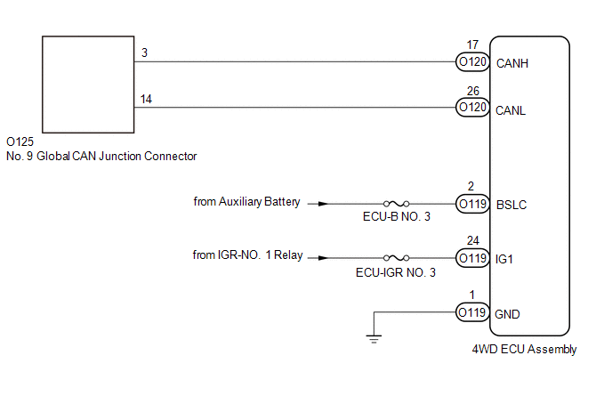
WIRING DIAGRAM
CAUTION / NOTICE / HINT
CAUTION:
When performing the confirmation driving pattern, obey all speed limits and traffic laws.
NOTICE:
-
Because the order of diagnosis is important to allow correct diagnosis, make sure to begin troubleshooting using How to Proceed with Troubleshooting when CAN communication system related DTCs are output.
Click here

- Before measuring the resistance of the CAN bus, turn the ignition switch off and leave the vehicle for 1 minute or more without operating the key or any switches, or opening or closing the doors. After that, disconnect the cable from the negative (-) auxiliary battery terminal and leave the vehicle for 1 minute or more before measuring the resistance.
-
After the ignition switch is turned off, there may be a waiting time before disconnecting the negative (-) auxiliary battery terminal.
Click here

-
When disconnecting and reconnecting the auxiliary battery, there is an automatic learning function that completes learning when the respective system is used.
Click here

-
Some parts must be initialized and set when replacing or removing and installing parts.
Click here

-
After performing repairs, perform the DTC check procedure and confirm that the DTCs are not output again.
DTC check procedure: Turn the ignition switch to ON and wait for 1 minute or more. Then operate the suspected malfunctioning system and drive the vehicle at 60 km/h (37 mph) or more for 5 minutes or more.
-
After the repair, perform the CAN bus check and check that all the ECUs and sensors connected to the CAN communication system are displayed as normal.
Click here

- Inspect the fuses for circuits related to this system before performing the following procedure.
HINT:
- Before disconnecting related connectors for inspection, push in on each connector body to check that the connector is not loose or disconnected.
- When a connector is disconnected, check that the terminals and connector body are not cracked, deformed or corroded.
PROCEDURE
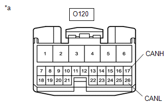
| 1. | CHECK FOR OPEN IN CAN BUS LINES (4WD ECU ASSEMBLY BRANCH LINE) |
(a) Disconnect the cable from the negative (-) battery terminal.
(b) Disconnect the 4WD ECU assembly connector.
| (c) Measure the resistance according to the value(s) in the table below. Standard Resistance:
|
|
| NG |
 | REPAIR OR REPLACE CAN BRANCH LINES OR CONNECTOR (4WD ECU ASSEMBLY) |
|

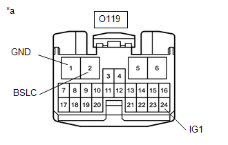
| 2. | CHECK HARNESS AND CONNECTOR (POWER SOURCE CIRCUIT) |
| (a) Measure the resistance according to the value(s) in the table below. Standard Resistance:
|
|
(b) Reconnect the cable to the negative (-) battery terminal.
(c) Measure the voltage according to the value(s) in the table below.
Standard Voltage:
| Tester Connection | Condition | Specified Condition |
|---|---|---|
| O119-2 (BSLC) - Body ground | Always | 11 to 14 V |
| O119-24 (IG1) - Body ground | Ignition switch ON | 11 to 14 V |
| OK |
 | REPLACE 4WD ECU ASSEMBLY |
| NG |
 | REPAIR OR REPLACE HARNESS OR CONNECTOR (POWER SOURCE CIRCUIT) |
 Engine Stop and Start ECU Communication Stop Mode
DESCRIPTION Detection Item Symptom Trouble Area Engine Stop and Start ECU Communication Stop Mode Communication stop for "Stop and Go/Start" is indicated on the "Communication Bus Check" screen of the GTS...
 Active Noise Control ECU Communication Stop Mode
DESCRIPTION Detection Item Symptom Trouble Area Active Noise Control ECU Communication Stop Mode Communication stop history for "Active Noise Control" is indicated on the "Communication Bus Check (Detail)" screen of the GTS...
Other information:
Toyota Yaris XP210 (2020-2026) Reapir and Service Manual: When Disconnecting Or Reconnecting Battery Terminal
Automatic Learning ChartAUTOMATIC LEARNING CHART AUTOMATIC LEARNING PERFORMED WHEN CABLE IS DISCONNECTED / RECONNECTED TO AUXILIARY BATTERY TERMINAL When the cable is disconnected / reconnected to the auxiliary battery terminal, systems temporarily stop operating...
Toyota Yaris XP210 (2020-2026) Reapir and Service Manual: G16e-gts Oil And Oil Filter
ComponentsCOMPONENTS ILLUSTRATION *1 OIL FILTER SUB-ASSEMBLY *2 OIL FILLER CAP ASSEMBLY *3 GASKET *4 OIL PAN DRAIN PLUG *5 REAR ENGINE UNDER COVER RH - - Tightening torque for "Major areas involving basic vehicle performance such as moving/turning/stopping": N*m (kgf*cm, ft...
Categories
- Manuals Home
- Toyota Yaris Owners Manual
- Toyota Yaris Service Manual
- Engine Start Function When Key Battery is Dead
- To Set Speed
- G16e-gts (engine Mechanical)
- New on site
- Most important about car
Keys

To use the auxiliary key, press the knob and pull out the auxiliary key from the smart key.
