Toyota Yaris: Can Communication System / Active Noise Control ECU Communication Stop Mode
DESCRIPTION
| Detection Item | Symptom | Trouble Area |
|---|---|---|
| Active Noise Control ECU Communication Stop Mode | Communication stop history for "Active Noise Control" is indicated on the "Communication Bus Check (Detail)" screen of the GTS. (The Lost Communication Time value for "Active Noise Control" is 6 or more.) Click here
|
|

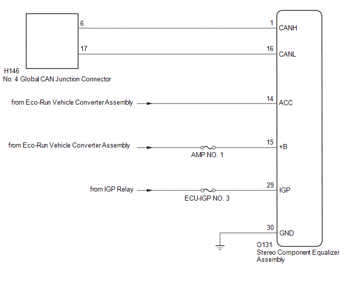
WIRING DIAGRAM
CAUTION / NOTICE / HINT
CAUTION:
When performing the confirmation driving pattern, obey all speed limits and traffic laws.
NOTICE:
-
Because the order of diagnosis is important to allow correct diagnosis, make sure to begin troubleshooting using How to Proceed with Troubleshooting when CAN communication system related DTCs are output.
Click here

- Before measuring the resistance of the CAN bus, turn the ignition switch off and leave the vehicle for 1 minute or more without operating the key or any switches, or opening or closing the doors. After that, disconnect the cable from the negative (-) auxiliary battery terminal and leave the vehicle for 1 minute or more before measuring the resistance.
-
After the ignition switch is turned off, there may be a waiting time before disconnecting the negative (-) auxiliary battery terminal.
Click here

-
When disconnecting and reconnecting the auxiliary battery, there is an automatic learning function that completes learning when the respective system is used.
Click here

-
Some parts must be initialized and set when replacing or removing and installing parts.
Click here

-
After performing repairs, perform the DTC check procedure and confirm that the DTCs are not output again.
DTC check procedure: Turn the ignition switch to ON and wait for 1 minute or more. Then operate the suspected malfunctioning system and drive the vehicle at 60 km/h (37 mph) or more for 5 minutes or more.
-
After the repair, perform the CAN bus check and check that all the ECUs and sensors connected to the CAN communication system are displayed as normal.
Click here

- Inspect the fuses for circuits related to this system before performing the following procedure.
HINT:
- Before disconnecting related connectors for inspection, push in on each connector body to check that the connector is not loose or disconnected.
- When a connector is disconnected, check that the terminals and connector body are not cracked, deformed or corroded.
PROCEDURE
| 1. | CHECK FOR OPEN IN CAN BUS WIRE (STEREO COMPONENT EQUALIZER ASSEMBLY BRANCH WIRE) |
(a) Disconnect the cable from the negative (-) battery terminal.
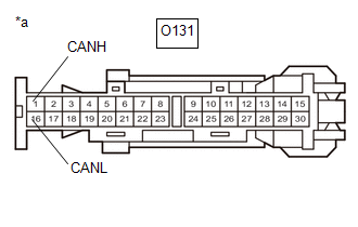
(b) Disconnect the stereo component equalizer assembly connector.
| (c) Measure the resistance according to the value(s) in the table below. Standard Resistance:
|
|
| NG |
 | REPAIR OR REPLACE CAN BRANCH LINES OR CONNECTOR (STEREO COMPONENT EQUALIZER ASSEMBLY) |
|

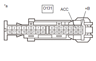
| 2. | CHECK HARNESS AND CONNECTOR (POWER SOURCE CIRCUIT) |
| (a) Measure the resistance according to the value(s) in the table below. Standard Resistance:
|
|
(b) Reconnect the cable to the negative (-) battery terminal.
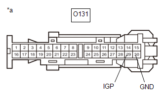
(c) Measure the voltage according to the value(s) in the table below.
Standard Voltage:
| Tester Connection | Condition | Specified Condition |
|---|---|---|
| O131-29 (IGP) - Body ground | Ignition switch ON | 11 to 14 V |
| NG |
 | REPAIR OR REPLACE HARNESS OR CONNECTOR (POWER SOURCE CIRCUIT) |
|

| 3. | CHECK HARNESS AND CONNECTOR (POWER SOURCE CIRCUIT) |
| (a) Measure the voltage according to the value(s) in the table below. Standard Voltage:
|
|
| OK |
 | REPLACE STEREO COMPONENT EQUALIZER ASSEMBLY |
| NG |
 | GO TO STOP AND START SYSTEM (BACKUP BOOST CONVERTER CIRCUIT) |
 4WD Control ECU Communication Stop Mode
DESCRIPTION Detection Item Symptom Trouble Area 4WD Control ECU Communication Stop Mode Communication stop for "Four Wheel Drive Control" is indicated on the "Communication Bus Check" screen of the GTS...
 Bus Buffer ECU Communication Stop Mode
DESCRIPTION Detection Item Symptom Trouble Area Bus Buffer ECU Communication Stop Mode Communication stop for "Remote Engine Starter" is indicated on the "Communication Bus Check" screen of the GTS...
Other information:
Toyota Yaris XP210 (2020-2026) Reapir and Service Manual: Removal
REMOVAL PROCEDURE 1. REMOVE PIN HOLD CLIP (a) Apply protective tape around the front bumper assembly. HINT: Use the same procedure for the RH side and LH side. Protective Tape (b) Using a screwdriver with its tip wrapped in protective tape, disengage the claws to remove the 2 pin hold clips...
Toyota Yaris XP210 (2020-2026) Reapir and Service Manual: Transmitter Battery
ComponentsCOMPONENTS ILLUSTRATION *1 MECHANICAL KEY *2 TRANSMITTER BATTERY *3 TRANSMITTER HOUSING CASE *4 TRANSMITTER HOUSING COVER RemovalREMOVAL CAUTION / NOTICE / HINT NOTICE: Take extra care when handling these precision electronic components...
Categories
- Manuals Home
- Toyota Yaris Owners Manual
- Toyota Yaris Service Manual
- Fuse Panel Description
- Adjustment
- Battery Monitor Module General Electrical Failure (P058A01)
- New on site
- Most important about car
Liftgate/Trunk Lid
WARNING
Never allow a person to ride in the luggage compartment/trunk
Allowing a person to ride in the luggage compartment/trunk is dangerous. The person in the luggage compartment/trunk could be seriously injured or killed during sudden braking or a collision.
Do not drive with the liftgate/trunk lid open