Toyota Yaris: Front Speed Sensor / Removal
REMOVAL
CAUTION / NOTICE / HINT
HINT:
- Use the same procedure for the RH side and LH side.
- The following procedure is for the LH side.
- The front speed sensor rotor is a component of the front axle hub sub-assembly. If the front speed sensor rotor is malfunctioning, replace the front axle hub sub-assembly.
PROCEDURE
1. REMOVE FRONT WHEEL
Click here

2. SEPARATE FRONT FENDER LINER
| (a) Remove the 6 clips, 3 screws and grommet to separate the front fender liner. |
|
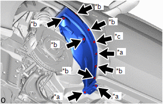
3. REMOVE FRONT SPEED SENSOR
(a) Turn back the front fender liner.
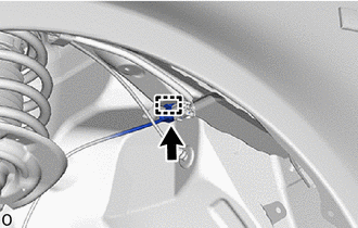
| (b) Disconnect the connector. |
|
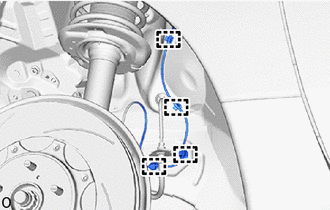
(c) Disengage the clamp from the vehicle body.
| (d) Disengage the 4 clamps from the vehicle body. |
|
| (e) Remove the bolt and hook to separate the front speed sensor. |
|
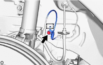
| (f) Remove the bolt and separate the front flexible hose and front speed sensor clamp from the front shock absorber assembly. |
|
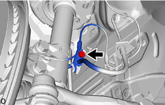
| (g) Disengage the clamp from the front shock absorber assembly. |
|
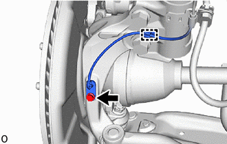
(h) Remove the bolt and front speed sensor from the steering knuckle.
NOTICE:
- Keep the tip of the front speed sensor and installation hole free of foreign matter.
- Do not rotate or apply excessive force to the front speed sensor when removing it from the steering knuckle. Rotating or applying excessive force may result in damage to the front speed sensor.
 Installation
INSTALLATION CAUTION / NOTICE / HINT HINT:
Use the same procedure for the RH side and LH side.
The following procedure is for the LH side.
The front speed sensor rotor is a component of the front axle hub sub-assembly...

Other information:
Toyota Yaris XP210 (2020-2026) Reapir and Service Manual: Internal Control Module Throttle Position Performance Internal Electronic Failure (P060E49)
MONITOR DESCRIPTION The ECM monitors the signals received from the No. 1 throttle position sensor. As the ECM monitors the VTA1 signal of the No. 1 throttle position sensor, if these signals do not correlate, a DTC will be stored. DTC No. Detection Item DTC Detection Condition Trouble Area MIL Note P060E49 Internal Control Module Throttle Position Performance Internal Electronic Failure Either of the following conditions is met (1 trip detection logic): ECM main CPU malfunction...
Toyota Yaris XP210 (2020-2026) Reapir and Service Manual: Removal
REMOVAL CAUTION / NOTICE / HINT HINT: When the cable is disconnected / reconnected to the auxiliary battery terminal, systems temporarily stop operating. However, each system has a function that completes learning the first time the system is used. Learning completes when vehicle is driven Effect/Inoperative Function When Necessary Procedures are not Performed Necessary Procedures Link Lane tracing assist system Drive the vehicle straight ahead at 35 km/h (22 mph) or more for 5 second or more...
Categories
- Manuals Home
- Toyota Yaris Owners Manual
- Toyota Yaris Service Manual
- Immobilizer System
- How to connect USB port/Auxiliary jack
- To Set Speed
- New on site
- Most important about car
Fuel Gauge
The fuel gauge shows approximately how much fuel is remaining in the tank when the ignition is switched ON. We recommend keeping the tank over 1/4 full.
