Toyota Yaris: Front Speed Sensor / Installation
INSTALLATION
CAUTION / NOTICE / HINT
HINT:
- Use the same procedure for the RH side and LH side.
- The following procedure is for the LH side.
- The front speed sensor rotor is a component of the front axle hub sub-assembly. If the front speed sensor rotor is malfunctioning, replace the front axle hub sub-assembly.
PROCEDURE
1. INSTALL FRONT SPEED SENSOR
(a) Install the front speed sensor to the steering knuckle with the bolt.
Torque:
8.5 N·m {87 kgf·cm, 75 in·lbf}
NOTICE:
- Keep the tip of the front speed sensor and installation hole free of foreign matter.
- Firmly insert the front speed sensor body into the steering knuckle before tightening the bolt.
- After installing the front speed sensor to the steering knuckle, make sure that there is no clearance between the front speed sensor stay and steering knuckle. Also make sure that no foreign matter is stuck between the parts.
| (b) Engage the clamp to the front shock absorber assembly. NOTICE: Do not twist the front speed sensor wire harness when installing it. |
|
(c) Engage the 2 hooks of front speed sensor clamp to the front shock absorber assembly.
NOTICE:
Do not twist the front speed sensor wire harness when installing it.
| (d) Install the front flexible hose to the front shock absorber assembly with the bolt. Torque: 29.4 N·m {300 kgf·cm, 22 ft·lbf} |
|
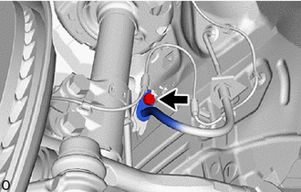
(e) Engage the hook to install the front speed sensor with the bolt.
Torque:
6.0 N·m {61 kgf·cm, 53 in·lbf}
NOTICE:
Do not twist the front speed sensor wire harness when installing it.
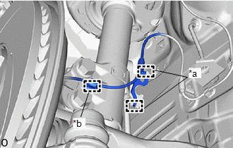
(f) Engage the 4 clamps to the vehicle body.
NOTICE:
Do not twist the front speed sensor wire harness when installing it.
(g) Engage the clamp to the vehicle body.
NOTICE:
Do not twist the front speed sensor wire harness when installing it.
(h) Connect the connector.
(i) Return the front fender liner to its original position.
2. INSTALL FRONT FENDER LINER
(a) Install the front fender liner with the 6 clips, 3 screws and grommet.
3. INSTALL FRONT WHEEL
Click here

4. CHECK FOR SPEED SENSOR SIGNAL
Click here

 Components
COMPONENTS ILLUSTRATION
*1 FRONT FENDER LINER *2 FRONT SPEED SENSOR *3 FRONT FLEXIBLE HOSE - -
Tightening torque for "Major areas involving basic vehicle performance such as moving/turning/stopping" : N*m (kgf*cm, ft...
 Removal
REMOVAL CAUTION / NOTICE / HINT HINT:
Use the same procedure for the RH side and LH side.
The following procedure is for the LH side.
The front speed sensor rotor is a component of the front axle hub sub-assembly...
Other information:
Toyota Yaris XP210 (2020-2026) Reapir and Service Manual: Steering Angle Sensor Module Component Internal Failure (C052696)
DESCRIPTION The skid control ECU (brake actuator assembly) outputs this DTC when it receives an internal malfunction signal from the steering sensor. DTC No. Detection Item DTC Detection Condition Trouble Area DTC Output from C052696 Steering Angle Sensor Module Component Internal Failure With the +BS terminal voltage 9...
Toyota Yaris XP210 (2020-2026) Owner's Manual: Manual Transaxle Shift Pattern
The shift pattern of the transaxle is conventional, as shown. Depress the clutch pedal all the way down while shifting; then release it slowly. Your vehicle is equipped with a device to prevent shifting to R (reverse) by mistake. Push the shift lever downward and shift to R...
Categories
- Manuals Home
- Toyota Yaris Owners Manual
- Toyota Yaris Service Manual
- Headlights
- Maintenance
- Engine Start Function When Key Battery is Dead
- New on site
- Most important about car
Fuel-Filler Lid and Cap
WARNING
When removing the fuel-filler cap, loosen the cap slightly and wait for any hissing to stop, then remove it
Fuel spray is dangerous. Fuel can burn skin and eyes and cause illness if ingested. Fuel spray is released when there is pressure in the fuel tank and the fuel-filler cap is removed too quickly.