Toyota Yaris: Manual Transaxle Operation / Manual Transaxle Shift Pattern
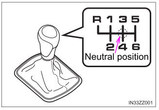
The shift pattern of the transaxle is conventional, as shown.
Depress the clutch pedal all the way down while shifting; then release it slowly.
Your vehicle is equipped with a device to prevent shifting to R (reverse) by mistake. Push the shift lever downward and shift to R.
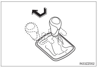
If shifting to R is difficult, shift back into neutral, release the clutch pedal, and try again.
WARNING
Do not use sudden engine braking on slippery road surfaces or at high speeds
Shifting down while driving on wet, snowy, or frozen roads, or while driving at high speeds causes sudden engine braking, which is dangerous. The sudden change in tire speed could cause the tires to skid. This could lead to loss of vehicle control and an accident.
Always leave the shift lever in 1 or R position and set the parking brake when leaving the vehicle unattended
Otherwise the vehicle could move and cause an accident.
NOTICE
- Keep your foot off the clutch pedal except when shifting gears. Also, do not use the clutch to hold the vehicle on an upgrade. Riding the clutch will cause needless clutch wear and damage.
- Do not apply any excessive lateral force to the shift lever when changing from 5th to 4th gear. This could lead to the accidental selection of 2nd gear, which could result in damage to the transaxle.
- Make sure the vehicle comes to a complete stop before shifting to R. Shifting to R while the vehicle is still moving may damage the transaxle.

 Gear Shift Indicator
The gear shift indicator supports you to obtain optimum fuel economy
and smooth driving. It displays the selected gear position in the combination
meter as well as notifies the driver to change to the most suitable gear
position corresponding to the actual driving condition...
Other information:
Toyota Yaris XP210 (2020-2026) Reapir and Service Manual: Customize Parameters
CUSTOMIZE PARAMETERS CUSTOMIZE SMART KEY SYSTEM (for Start Function) NOTICE: When the customer requests a change in a function, first make sure that the function can be customized. Record the current settings before customizing. HINT: The following items can be customized...
Toyota Yaris XP210 (2020-2026) Reapir and Service Manual: Recirculated/Fresh Air Modes Switch without User Input
DESCRIPTION If recirculation/fresh mode changes unintentionally and without permission, the following causes are possible. Symptom Factor Recirculation/fresh mode changes without permission Recirculation/fresh mode light blinks Customize setting Change in ambient air temperature Decrease in refrigerant pressure Air conditioner pressure sensor circuit malfunction Engine coolant temperature (high) PROCEDURE 1...
Categories
- Manuals Home
- Toyota Yaris Owners Manual
- Toyota Yaris Service Manual
- Key Battery Replacement
- How to connect USB port/Auxiliary jack
- G16e-gts (engine Mechanical)
- New on site
- Most important about car
Keys

To use the auxiliary key, press the knob and pull out the auxiliary key from the smart key.
