
Toyota Yaris: Stop Light Switch / Installation
INSTALLATION
PROCEDURE
1. INSTALL STOP LIGHT SWITCH MOUNTING ADJUSTER
| (a) Engage the claws to install a new stop light switch mounting adjuster. |
|

2. INSTALL STOP LIGHT SWITCH ASSEMBLY
| (a) Insert the stop light switch assembly to the stop light switch mounting adjuster until the switch body slightly touches the brake pedal. NOTICE: Do not depress the brake pedal. |
|

| (b) Turn the stop light switch assembly clockwise by approximately one fourth of a rotation. |
|
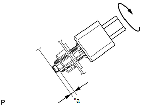
(c) Check the protrusion amount of the shaft.
Standard:
0.6 to 2.5 mm (0.0236 to 0.0984 in.)
(d) Connect the connector.
3. INSTALL NO. 1 INSTRUMENT PANEL UNDER COVER SUB-ASSEMBLY
Click here

 Removal
REMOVAL PROCEDURE 1. REMOVE NO. 1 INSTRUMENT PANEL UNDER COVER SUB-ASSEMBLY Click here
2. REMOVE STOP LIGHT SWITCH ASSEMBLY (a) Disconnect the connector...

Other information:
Toyota Yaris XP210 (2020-2026) Reapir and Service Manual: A/C Switch Indicator does not Turn On
DESCRIPTION If none of the switch indicators on the air conditioning control assembly illuminate, the following factors may be the cause. Symptom Factor A/C switch indicator does not illuminate Vehicle control history (RoB) Air conditioning amplifier assembly malfunction Air conditioning control assembly malfunction A/C switch malfunction A/C switch indicator malfunction (including when indicator turned off without switch operation) Servo motor initialization (incomplete) Mechanical locking of damper and damper link Refrigerant pressure is extremely low Low detected ambient temperature (including thermistor assembly malfunction) PROCEDURE 1...
Toyota Yaris XP210 (2020-2026) Reapir and Service Manual: Components
COMPONENTS ILLUSTRATION *1 FRONT BUMPER ASSEMBLY *2 PIN HOLD CLIP ILLUSTRATION *A w/ Pre-collision System - - *1 NO. 3 ENGINE ROOM WIRE *2 MILLIMETER WAVE RADAR SENSOR ASSEMBLY N*m (kgf*cm, ft.*lbf): Specified torque - - ILLUSTRATION *1 FOG LIGHT COVER LH *2 FOG LIGHT COVER RH *3 FOG LIGHT ASSEMBLY LH *4 FOG LIGHT ASSEMBLY RH *5 FRONT BUMPER HOLE COVER *6 HOOD TO FRONT END PANEL SEAL *7 LOWER RADIATOR GRILLE SUB-ASSEMBLY *8 RADIATOR GRILLE SIDE MOULDING LH *9 RADIATOR GRILLE SIDE MOULDING RH *10 RADIATOR GRILLE EMBLEM ASSEMBLY *11 FRONT BUMPER EXTENSION MOUNTING BRACKET - - ILLUSTRATION *1 FRONT BUMPER ENERGY ABSORBER *2 FRONT BUMPER SIDE RETAINER RH *3 RADIATOR UPPER AIR GUIDE PLATE *4 HEADLIGHT ASSEMBLY RH *5 HEADLIGHT ASSEMBLY LH *6 FRONT BUMPER SIDE RETAINER LH *7 FRONT BUMPER REINFORCEMENT *8 THERMISTOR ASSEMBLY *9 COOL AIR INTAKE DUCT - - N*m (kgf*cm, ft...
Categories
- Manuals Home
- Toyota Yaris Owners Manual
- Toyota Yaris Service Manual
- Brake System Control Module "A" System Voltage System Voltage Low (C137BA2)
- Engine & Hybrid System
- How to connect USB port/Auxiliary jack
- New on site
- Most important about car
Key Suspend Function
If a key is left in the vehicle, the functions of the key left in the vehicle are temporarily suspended to prevent theft of the vehicle.
To restore the functions, press the unlock button on the functions-suspended key in the vehicle.
