
Toyota Yaris: Lighting System / Turn Signal Switch Circuit
DESCRIPTION
The steering sensor receives the turn signal switch information and controls the turn signal lights.
WIRING DIAGRAM
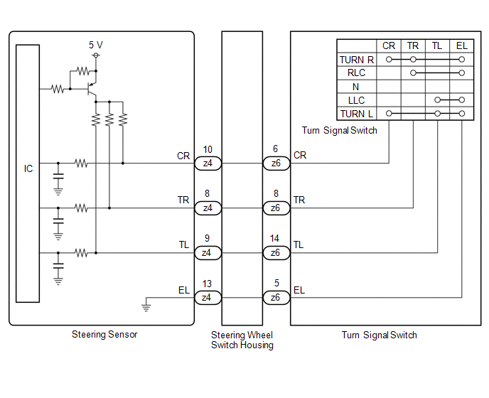
PROCEDURE
| 1. | READ VALUE USING GTS |
(a) Read the Data List according to the display on the GTS.
Chassis > Steering Angle Sensor > Data List| Tester Display | Measurement Item | Range | Normal Condition | Diagnostic Note |
|---|---|---|---|---|
| Turn Signal Switch (Right) | Turn signal switch (right) signal | OFF or ON | OFF: Turn signal switch not in right turn position ON: Turn signal switch in right turn position | - |
| Turn Signal Switch (Left) | Turn signal switch (left) signal | OFF or ON | OFF: Turn signal switch not in left turn position ON: Turn signal switch in left turn position | - |
| Cornering Light/Front Side Illuminate Light Switch | Turn signal switch (full turn) signal | OFF or ON | OFF: Turn signal switch not in left or right turn position ON: Turn signal switch in left or right full turn position | - |
OK:
Normal conditions listed above are displayed.
Chassis > Steering Angle Sensor > Data List| Tester Display |
|---|
| Turn Signal Switch (Right) |
| Turn Signal Switch (Left) |
| Cornering Light/Front Side Illuminate Light Switch |
| OK |
.gif) | PROCEED TO NEXT SUSPECTED AREA SHOWN IN PROBLEM SYMPTOMS TABLE |
|
.gif)
| 2. | INSPECT TURN SIGNAL SWITCH |
Click here
.gif)
| NG |
| REPLACE TURN SIGNAL SWITCH |
|
| 3. | INSPECT STEERING WHEEL SWITCH HOUSING |
Click here
| OK |
| REPLACE STEERING SENSOR |
| NG |
| REPLACE STEERING WHEEL SWITCH HOUSING |
 Lost Communication with Cruise Control Front Distance Range Sensor Signal Sensor or Center Missing Message (U023587)
DESCRIPTION The forward recognition camera and millimeter wave radar sensor assembly communicate via CAN communication. If there is an error in the communication with the millimeter wave radar sensor assembly, the forward recognition camera stores DTC U023587...
 Automatic High Beam Switch Indicator does not Come ON
DESCRIPTION When the automatic high beam system is on, the main body ECU (multiplex network body ECU) illuminates the auto high beam switch indicator. WIRING DIAGRAM
CAUTION / NOTICE / HINT NOTICE:
Inspect the fuses for circuits related to this system before performing the following procedure...
Other information:
Toyota Yaris XP210 (2020-2026) Owner's Manual: Interior Lights
Overhead Lights OFF DOOR ON Map Lights When the overhead light switch is in the door or off position, press the lens to illuminate the map lights, and then press the lens again to turn them off. Luggage Compartment Lights (5-Door) Trunk Light (4-Door) The trunk light is on when the lid is open and off when it’s closed...
Toyota Yaris XP210 (2020-2026) Reapir and Service Manual: Horn
ComponentsCOMPONENTS ILLUSTRATION *1 LOW PITCHED HORN ASSEMBLY *2 RADIATOR UPPER AIR GUIDE PLATE N*m (kgf*cm, ft.*lbf): Specified torque - - RemovalREMOVAL PROCEDURE 1. REMOVE FRONT BUMPER ASSEMBLY Click here 2. REMOVE RADIATOR UPPER AIR GUIDE PLATE Click here 3...
Categories
- Manuals Home
- Toyota Yaris Owners Manual
- Toyota Yaris Service Manual
- How to use USB mode
- To Set Speed
- Fuse Panel Description
- New on site
- Most important about car
Front Seat Belt Pretensioners
The front seat belt pretensioners are designed to deploy in moderate or severe frontal, near frontal collisions.
In addition, the pretensioners operate when a side collision or a rollover accident is detected. The pretensioners operate differently depending on what types of air bags are equipped. For more details about the seat belt pretensioner operation, refer to the SRS Air Bag Deployment Criteria.
