Toyota Yaris: Lighting System / Automatic High Beam Switch Indicator does not Come ON
DESCRIPTION
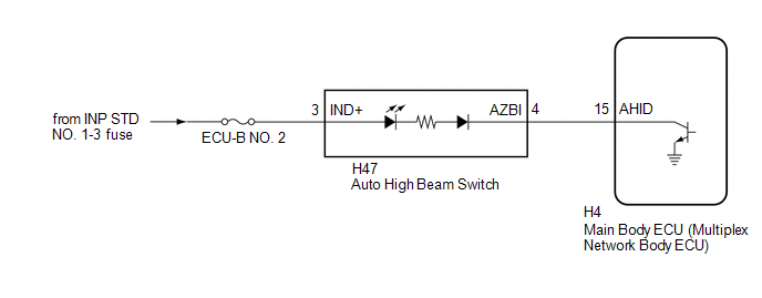
When the automatic high beam system is on, the main body ECU (multiplex network body ECU) illuminates the auto high beam switch indicator.
WIRING DIAGRAM
CAUTION / NOTICE / HINT
NOTICE:
- Inspect the fuses for circuits related to this system before performing the following procedure.
-
Before replacing the main body ECU (multiplex network body ECU), refer to Registration.
Click here
.gif)
PROCEDURE
| 1. | PERFORM ACTIVE TEST USING GTS |
(a) Perform the Active Test according to the display on the GTS.
Body Electrical > Main Body > Data List| Tester Display | Measurement Item | Range | Diagnostic Note |
|---|---|---|---|
| Automatic High Beam Switch Light | Auto high beam switch indicator light | OFF or ON | - |
| Tester Display |
|---|
| Automatic High Beam Switch Light |
OK:
Auto high beam switch indicator light illuminates.
| OK |
.gif) | USE SIMULATION METHOD TO CHECK |
|
.gif)
| 2. | INSPECT AUTO HIGH BEAM SWITCH |
Click here
| NG |
| REPLACE AUTO HIGH BEAM SWITCH |
|
| 3. | CHECK HARNESS AND CONNECTOR (POWER SOURCE - AUTO HIGH BEAM SWITCH) |
(a) Measure the voltage according to the value(s) in the table below.
Standard Voltage:
| Tester Connection | Switch Condition | Specified Condition |
|---|---|---|
| H47-3 (IND+) - Body ground | Ignition switch off | 11 to 14 V |
| NG |
| REPAIR OR REPLACE HARNESS OR CONNECTOR |
|
| 4. | CHECK HARNESS AND CONNECTOR (AUTO HIGH BEAM SWITCH - MAIN BODY ECU (MULTIPLEX NETWORK BODY ECU)) |
(a) Disconnect the H4 main body ECU (multiplex network body ECU) connector.
(b) Measure the resistance according to the value(s) in the table below.
Standard Resistance:
| Tester Connection | Condition | Specified Condition |
|---|---|---|
| H47-4 (AZBI) - H4-15 (AHID) | Always | Below 1 Ω |
| H47-4 (AZBI) or H4-15 (AHID) - Body ground | Always | 10 kΩ or higher |
| OK |
| REPLACE MAIN BODY ECU (MULTIPLEX NETWORK BODY ECU) |
| NG |
| REPAIR OR REPLACE HARNESS OR CONNECTOR |
 Turn Signal Switch Circuit
DESCRIPTION The steering sensor receives the turn signal switch information and controls the turn signal lights. WIRING DIAGRAM
PROCEDURE 1. READ VALUE USING GTS (a) Read the Data List according to the display on the GTS...
 Automatic High Beam System does not Operate or Operation Indicator does not Illuminate
DESCRIPTION The main body ECU (multiplex network body ECU) controls the automatic high beam system based on signals received from the forward recognition camera...
Other information:
Toyota Yaris XP210 (2020-2026) Reapir and Service Manual: Components
COMPONENTS ILLUSTRATION *A for Front Passenger Side *B for Driver Side *1 FRONT DOOR LOWER FRAME BRACKET GARNISH *2 MULTIPLEX NETWORK MASTER SWITCH ASSEMBLY WITH FRONT ARMREST BASE UPPER PANEL *3 POWER WINDOW REGULATOR SWITCH ASSEMBLY WITH FRONT ARMREST BASE UPPER PANEL *4 FRONT DOOR TRIM GARNISH *5 FRONT DOOR TRIM BOARD SUB-ASSEMBLY *6 FRONT DOOR GLASS INNER WEATHERSTRIP *7 OUTER REAR VIEW MIRROR ASSEMBLY - - N*m (kgf*cm, ft...
Toyota Yaris XP210 (2020-2026) Reapir and Service Manual: Installation
INSTALLATION PROCEDURE 1. INSTALL NO. 2 FUEL SENDER GAUGE ASSEMBLY (a) Attach the claw and install the No. 2 fuel sender gauge assembly. NOTICE: Be careful not to bend the arm of the fuel sender gauge assembly. (b) Attach the 2 clamps and connect the wire harness to the fuel tank vent tube assembly...
Categories
- Manuals Home
- Toyota Yaris Owners Manual
- Toyota Yaris Service Manual
- Immobilizer System
- Opening and Closing the Liftgate/Trunk Lid
- Battery Monitor Module General Electrical Failure (P058A01)
- New on site
- Most important about car
Keys

To use the auxiliary key, press the knob and pull out the auxiliary key from the smart key.
