Toyota Yaris: Sfi System / Camshaft Position "B" - Timing Over-Advanced or System Performance Bank 1 (P001400,P001500)
DESCRIPTION
Refer to DTC P001313.
Click here

| DTC No. | Detection Item | DTC Detection Condition | Trouble Area | MIL | Note |
|---|---|---|---|---|---|
| P001400 | Camshaft Position "B" - Timing Over-Advanced or System Performance Bank 1 | Exhaust valve timing is stuck at a certain value when in the advance range (2 trip detection logic). |
| Comes on | SAE: P0014 |
| P001500 | Camshaft Position "B" - Timing Over-Retarded Bank 1 | Exhaust valve timing is stuck at a certain value when in the retard range (1 trip detection logic). |
| Comes on | SAE: P0015 |
MONITOR DESCRIPTION
The ECM optimizes the exhaust valve timing using the Variable Valve Timing (VVT) system to control the exhaust camshaft. The VVT system includes the ECM, cam timing oil control solenoid assembly, camshaft timing oil control valve assembly (exhaust camshaft timing gear bolt assembly) and camshaft timing exhaust gear assembly. The ECM sends a target duty-cycle control signal to the cam timing oil control solenoid assembly. The camshaft timing oil control valve assembly (exhaust camshaft timing gear bolt assembly) is operated to control the oil pressure supplied to the camshaft timing exhaust gear assembly based on this signal. The camshaft timing gear assembly can advance or retard the exhaust camshaft.
If the difference between the target and actual exhaust valve timing is large, and changes in the actual exhaust valve timing are small, the ECM interprets this as the camshaft timing exhaust gear assembly stuck malfunction and stores a DTC.
- Example:
-
A DTC is stored when the following conditions are met:
- It takes 5 seconds or more to change the valve timing by 5°CA.
- After the above condition is met, the cam timing oil control solenoid assembly is forcibly activated for 9.5 seconds.
These DTCs indicate that the camshaft timing exhaust gear assembly cannot operate properly due to a camshaft timing oil control valve assembly (exhaust camshaft timing gear bolt assembly) malfunction or the presence of foreign matter in the camshaft timing oil control valve assembly (exhaust camshaft timing gear bolt assembly).
MONITOR STRATEGY
| Required Sensors/Components (Main) | Cam timing oil control solenoid assembly Camshaft timing oil control valve assembly (exhaust camshaft timing gear bolt assembly) Camshaft timing exhaust gear assembly |
| Required Sensors/Components (Related) | Crankshaft position sensor Camshaft position sensor Engine coolant temperature sensor |
| Frequency of Operation | Continuous |
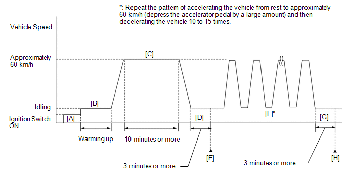
CONFIRMATION DRIVING PATTERN
- Connect the GTS to the DLC3.
- Turn the ignition switch to ON.
- Turn the GTS on.
- Clear the DTCs (even if no DTCs are stored, perform the clear DTC procedure).
- Turn the ignition switch off and wait for at least 30 seconds.
- Turn the ignition switch to ON [A].
- Turn the GTS on.
- Start the engine and warm it up until the engine coolant temperature reaches 75°C (167°F) or higher [B].
-
Drive the vehicle at approximately 60 km/h (37 mph) for 10 minutes or more [C].
CAUTION:
When performing the confirmation driving pattern, obey all speed limits and traffic laws.
- Idle the engine for 3 minutes or more [D].
- Enter the following menus: Powertrain / Engine / Trouble Codes [E].
-
Read the pending DTCs.
HINT:
- If a pending DTC is output, the system is malfunctioning.
- If a pending DTC is not output, perform the following procedure.
- Enter the following menus: Powertrain / Engine / Utility / All Readiness.
- Input the DTC: P001400 or P001500.
-
Check the DTC judgment result.
GTS Display
Description
NORMAL
- DTC judgment completed
- System normal
ABNORMAL
- DTC judgment completed
- System abnormal
INCOMPLETE
- DTC judgment not completed
- Perform driving pattern after confirming DTC enabling conditions
HINT:
- If the judgment result is NORMAL, the system is normal.
- If the judgment result is ABNORMAL, the system has a malfunction.
- If the judgment result is INCOMPLETE, perform steps [F] through [H].
-
Repeat the pattern of accelerating the vehicle from rest to approximately 60 km/h (37 mph) and then decelerating the vehicle 10 to 15 times [F].
CAUTION:
When performing the confirmation driving pattern, obey all speed limits and traffic laws.
HINT:
Depress the accelerator pedal by a large amount.
- Idle the engine for 3 minutes or more [G].
- Enter the following menus: Powertrain / Engine / Trouble Codes [H].
-
Read the pending DTCs.
HINT:
- If a pending DTC is output, the system is malfunctioning.
- If a pending DTC is not output, perform the following procedure.
-
Check the DTC judgment result again.
HINT:
- If the judgment result is NORMAL, the system is normal.
- If the judgment result is ABNORMAL, the system has a malfunction.
WIRING DIAGRAM
Refer to DTC P001313.
Click here

CAUTION / NOTICE / HINT
HINT:
- DTC P001400 or P001500 may be stored when foreign matter in the engine oil is caught in some parts of the system. The DTC will remain stored even if the system returns to normal after a short time. This foreign matter may then be captured by the oil filter.
- Read Freeze Frame Data using the GTS. The ECM records vehicle and driving condition information as Freeze Frame Data the moment a DTC is stored. When troubleshooting, Freeze Frame Data can help determine if the vehicle was moving or stationary, if the engine was warmed up or not, if the air fuel ratio was lean or rich, and other data from the time the malfunction occurred.
PROCEDURE
| 1. | CHECK ANY OTHER DTCS OUTPUT (IN ADDITION TO DTC P001400 OR P001500) |
(a) Read the DTCs.
Powertrain > Engine > Trouble Codes| Result | Proceed to |
|---|---|
| P001400 or P001500 and other DTCs are output | A |
| P001400 or P001500 is output | B |
HINT:
If any DTCs other than P001400 or P001500 are output, troubleshoot those DTCs first.
| A |
 | GO TO DTC CHART |
|

| 2. | PERFORM ACTIVE TEST USING GTS (CONTROL THE EXHAUST VVT OCV DUTY RATIO BANK 1) |
(a) Start the engine.
(b) Check the engine speed while operating the cam timing oil control solenoid assembly using the GTS.
Powertrain > Engine > Active Test| Active Test Display |
|---|
| Control the Exhaust VVT OCV Duty Ratio Bank 1 |
| Data List Display |
|---|
| Exhaust VVT OCV Control Duty Ratio Bank 1 |
Standard:
| GTS Operation | Engine Condition |
|---|---|
| 0% | Normal engine speed |
| 100% | Engine idles roughly or stalls |
HINT:
Refer to "Data List / Active Test" [Exhaust VVT Hold Learn Value Bank 1, Exhaust VVT Change Angle Bank 1, Exhaust VVT OCV Control Duty Ratio Bank 1 and Exhaust VVT Target Angle Bank 1].
Click here

| NG |
 | GO TO STEP 5 |
|

| 3. | CLEAR DTC |
(a) Clear the DTCs.
Powertrain > Engine > Clear DTCs(b) Turn the ignition switch off and wait for at least 30 seconds.
|

| 4. | CHECK WHETHER DTC OUTPUT RECURS (DTC P001400 OR P001500) |
(a) Drive the vehicle in accordance with the driving pattern described in Confirmation Driving Pattern.
(b) Read the DTCs.
Powertrain > Engine > Trouble Codes| Result | Proceed to |
|---|---|
| DTCs are not output | A |
| P001400 or P001500 is output | B |
HINT:
DTC P001400 or P001500 may be stored when foreign matter in the engine oil is caught in some parts of the system. The DTC will remain stored even if the system returns to normal after a short time. That foreign matter may then be captured by the oil filter.
| A |
 | CHECK FOR INTERMITTENT PROBLEMS |
|

| 5. | INSPECT CAM TIMING OIL CONTROL SOLENOID ASSEMBLY (FOR EXHAUST CAMSHAFT) |
Click here

| NG |
 | GO TO STEP 8 |
|

| 6. | INSPECT CAMSHAFT TIMING VALVE ASSEMBLY (EXHAUST CAMSHAFT TIMING OIL CONTROL VALVE) |
Click here

| NG |
 | GO TO STEP 10 |
|

| 7. | CHECK VALVE TIMING (CHECK FOR LOOSE AND JUMPED TEETH ON TIMING CHAIN) |
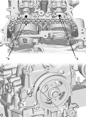
| *a | Timing Mark |
| *b | TDC Timing Mark |
| *c | Groove |
(a) Remove the cylinder head cover sub-assembly.
(b) Turn the crankshaft pulley and align its groove with the TDC timing mark of the timing chain cover.
(c) Check that the timing marks of the camshaft timing gear assembly and camshaft timing exhaust gear assembly are at the positions shown in the illustration.
HINT:
If the timing marks are not as shown, turn the crankshaft one revolution clockwise.
OK:
Timing marks on camshaft timing gear assembly and camshaft timing exhaust gear assembly are at the positions shown in the illustration.
HINT:
If the result is not as specified, check for mechanical malfunctions that may have affected the valve timing, such as a jumped tooth or stretching of the timing chain.
| OK |
 | GO TO STEP 12 |
| NG |
 | REPAIR OR REPLACE MALFUNCTIONING PARTS, COMPONENT AND AREA |
| 8. | REPLACE CAM TIMING OIL CONTROL SOLENOID ASSEMBLY |
HINT:
Click here

|

| 9. | INSPECT CAMSHAFT TIMING VALVE ASSEMBLY (EXHAUST CAMSHAFT TIMING OIL CONTROL VALVE) |
HINT:
Click here

| OK |
 | GO TO STEP 11 |
|

| 10. | REPLACE CAMSHAFT TIMING VALVE ASSEMBLY (EXHAUST CAMSHAFT TIMING OIL CONTROL VALVE) |
HINT:
Click here

|

| 11. | PERFORM ACTIVE TEST USING GTS (CONTROL THE EXHAUST VVT OCV DUTY RATIO BANK 1) |
(a) Start the engine.
(b) Check the engine speed while operating the cam timing oil control solenoid assembly using the GTS.
Powertrain > Engine > Active Test| Active Test Display |
|---|
| Control the Exhaust VVT OCV Duty Ratio Bank 1 |
| Data List Display |
|---|
| Intake VVT OCV Control Duty Ratio Bank 1 |
Standard:
| GTS Operation | Engine Condition |
|---|---|
| 0% | Normal engine speed |
| 100% | Engine idles roughly or stalls |
HINT:
Refer to "Data List / Active Test" [Exhaust VVT Hold Learn Value Bank 1, Exhaust VVT Change Angle Bank 1, Exhaust VVT OCV Control Duty Ratio Bank 1 and Exhaust VVT Target Angle Bank 1].
Click here

| OK |
 | END |
|

| 12. | REPLACE CAMSHAFT TIMING EXHAUST GEAR ASSEMBLY |
HINT:
Click here

Perform "Inspection After Repair" after replacing the camshaft timing exhaust gear assembly.
Click here

|

| 13. | CLEAR DTC |
(a) Clear the DTCs.
Powertrain > Engine > Clear DTCs(b) Turn the ignition switch off and wait for at least 30 seconds.
|

| 14. | CHECK WHETHER DTC OUTPUT RECURS (DTC P001400 OR P001500) |
(a) Drive the vehicle in accordance with the driving pattern described in Confirmation Driving Pattern.
(b) Read the DTCs.
Powertrain > Engine > Trouble Codes| Result | Proceed to |
|---|---|
| DTCs are not output | A |
| P001400 or P001500 is output | B |
| A |
 | END |
| B |
 | REPLACE ECM |
 Camshaft Position "B" - Actuator Bank 1 Circuit Open (P001313)
DESCRIPTION The Variable Valve Timing (VVT) system adjusts the exhaust valve timing to improve driveability. The engine oil pressure turns the VVT controller (camshaft timing exhaust gear assembly) to adjust the valve timing...
 Crankshaft Position - Camshaft Position Correlation Bank 1 Sensor A (P001600,P001700)
DESCRIPTION In the VVT (Variable Valve Timing) system, the appropriate intake and exhaust valve open and close timing is controlled by the ECM. The ECM performs intake and exhaust valve control by performing the following: 1) controlling the camshaft, cam timing oil control solenoid assembly, camshaft timing gear bolt (camshaft timing oil control valve) and operating the camshaft timing gear; and 2) changing the relative positions of the camshaft and crankshaft...
Other information:
Toyota Yaris XP210 (2020-2025) Reapir and Service Manual: Data List / Active Test
DATA LIST / ACTIVE TEST DATA LIST (a) Perform the Active Test according to the display on the GTS. Body Electrical > Power Distribution Box > Data List Tester Display Measurement Item Range Normal Condition Diagnostic Note Rear Defogger Input Signal Window defogger switch signal input condition ON or OFF ON: Window defogger switch is on OFF: Window defogger switch is off - Rear Defogger Output Signal Window defogger output condition ON or OFF ON: Window defogger operates OFF: Window defogger does not operate - Rear Defogger Output Current Window defogger current Min...
Toyota Yaris XP210 (2020-2025) Owner's Manual: Settings
Select the icon on the home screen and display the Settings screen. Switch the tab and select the setting item you want to change. You can customize settings in the setup display as follows: Depending on the grade and specification, the screen display may differ...
Categories
- Manuals Home
- Toyota Yaris Owners Manual
- Toyota Yaris Service Manual
- Key Battery Replacement
- How to connect USB port/Auxiliary jack
- Power Integration No.1 System Missing Message (B235287,B235587,B235787-B235987)
- New on site
- Most important about car
Fuel Gauge
The fuel gauge shows approximately how much fuel is remaining in the tank when the ignition is switched ON. We recommend keeping the tank over 1/4 full.
