Toyota Yaris: Sfi System / Camshaft Position "B" - Actuator Bank 1 Circuit Open (P001313)
DESCRIPTION
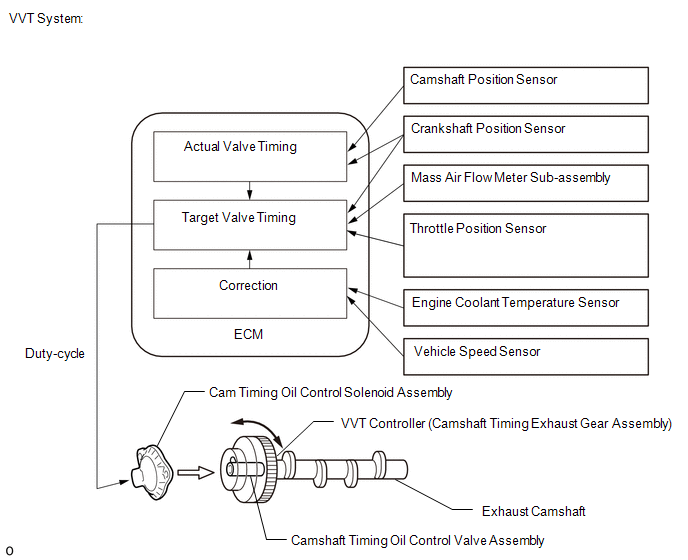
The Variable Valve Timing (VVT) system adjusts the exhaust valve timing to improve driveability. The engine oil pressure turns the VVT controller (camshaft timing exhaust gear assembly) to adjust the valve timing.
The cam timing oil control solenoid assembly (for exhaust camshaft) operates according to signals received from the ECM to control the position of the camshaft timing oil control valve assembly (exhaust camshaft timing gear bolt assembly) and supply engine oil. The camshaft timing oil control valve assembly (exhaust camshaft timing gear bolt assembly) moves when the ECM applies 12 V to the cam timing oil control solenoid assembly (for exhaust camshaft). The ECM changes the energizing time of the cam timing oil control solenoid assembly (for exhaust camshaft) duty-cycle in accordance with the camshaft position, crankshaft position, throttle position, etc.
| DTC No. | Detection Item | DTC Detection Condition | Trouble Area | MIL | Note |
|---|---|---|---|---|---|
| P001313 | Camshaft Position "B" - Actuator Bank 1 Circuit Open | Open or short in cam timing oil control solenoid assembly (for exhaust camshaft) circuit (1 trip detection logic). |
| Comes on | SAE: P0013 |
MONITOR DESCRIPTION
These DTCs are designed to detect an open or short in the cam timing oil control solenoid assembly (for exhaust camshaft) circuit. If the cam timing oil control solenoid assembly (for exhaust camshaft) duty-cycle is excessively high or low while the ignition switch is ON or the engine is running, the ECM will illuminate the MIL and store this DTC.
CONFIRMATION DRIVING PATTERN
- Connect the GTS to the DLC3.
- Turn the ignition switch to ON.
- Turn the GTS on.
- Clear the DTCs (even if no DTCs are stored, perform the clear DTC procedure).
- Turn the ignition switch off and wait for at least 30 seconds.
- Start the engine [A].
- Wait 5 seconds or more [B].
- Turn the GTS on.
- Enter the following menus: Powertrain / Engine / Trouble Codes [C].
-
Read the pending DTCs.
HINT:
- If a pending DTC is output, the system is malfunctioning.
- If a pending DTC is not output, perform the following procedure.
- Enter the following menus: Powertrain / Engine / Utility / All Readiness.
- Input the DTC: P001313.
-
Check the DTC judgment result.
GTS Display
Description
NORMAL
- DTC judgment completed
- System normal
ABNORMAL
- DTC judgment completed
- System abnormal
INCOMPLETE
- DTC judgment not completed
- Perform driving pattern after confirming DTC enabling conditions
HINT:
- If the judgment result is NORMAL, the system is normal.
- If the judgment result is ABNORMAL, the system has a malfunction.
- If the judgment result is INCOMPLETE, perform steps [A] through [C] again.
WIRING DIAGRAM
CAUTION / NOTICE / HINT
HINT:
Read Freeze Frame Data using the GTS. The ECM records vehicle and driving condition information as Freeze Frame Data the moment a DTC is stored. When troubleshooting, Freeze Frame Data can help determine if the vehicle was moving or stationary, if the engine was warmed up or not, if the air fuel ratio was lean or rich, and other data from the time the malfunction occurred.
PROCEDURE
| 1. | CLEAR DTC |
(a) Record the Freeze Frame Data.
Powertrain > Engine > Trouble Codes(b) Clear the DTCs.
Powertrain > Engine > Clear DTCs(c) Turn the ignition switch off and wait for at least 30 seconds.
|

| 2. | READ OUTPUT DTC (DTC P001313) |
(a) Start the engine.
(b) Read the DTCs.
Powertrain > Engine > Trouble Codes| Result | Proceed to |
|---|---|
| DTCs are not output | A |
| P001313 is output | B |
| A |
 | CHECK FOR INTERMITTENT PROBLEMS |
|

| 3. | INSPECT CAM TIMING OIL CONTROL SOLENOID ASSEMBLY |
Click here

| NG |
 | REPLACE CAM TIMING OIL CONTROL SOLENOID ASSEMBLY |
|

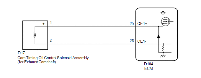
| 4. | CHECK HARNESS AND CONNECTOR (CAM TIMING OIL CONTROL SOLENOID ASSEMBLY (FOR EXHAUST CAMSHAFT) - ECM) |
(a) Disconnect the cam timing oil control solenoid assembly (for exhaust camshaft) connector.
(b) Disconnect the ECM connector.
(c) Measure the resistance according to the value(s) in the table below.
Standard Resistance:
| Tester Connection | Condition | Specified Condition |
|---|---|---|
| D17-1(+) - D104-25(OE1+) | Always | Below 1 Ω |
| D17-2(-) - D104-26(OE1-) | Always | Below 1 Ω |
| D17-1(+) or D104-25(OE1+) - Body ground and other terminals | Always | 10 kΩ or higher |
| D17-2(-) or D104-26(OE1-) - Body ground and other terminals | Always | 10 kΩ or higher |
| OK |
 | REPLACE ECM |
| NG |
 | REPAIR OR REPLACE HARNESS OR CONNECTOR |
 Camshaft Position "A" - Timing Over-Advanced or System Performance Bank 1 (P001100,P001200)
DESCRIPTION Refer to DTC P001013. Click here
DTC No. Detection Item DTC Detection Condition Trouble Area MIL Note P001100 Camshaft Position "A" - Timing Over-Advanced or System Performance Bank 1 Intake valve timing is stuck at a certain value when in the advance range (1 trip detection logic)...
 Camshaft Position "B" - Timing Over-Advanced or System Performance Bank 1 (P001400,P001500)
DESCRIPTION Refer to DTC P001313. Click here
DTC No. Detection Item DTC Detection Condition Trouble Area MIL Note P001400 Camshaft Position "B" - Timing Over-Advanced or System Performance Bank 1 Exhaust valve timing is stuck at a certain value when in the advance range (2 trip detection logic)...
Other information:
Toyota Yaris XP210 (2020-2026) Reapir and Service Manual: How To Proceed With Troubleshooting
CAUTION / NOTICE / HINT HINT: Before performing troubleshooting for the front radar sensor system, perform troubleshooting for the pre-collision system. Click here *: Use the GTS. PROCEDURE 1. VEHICLE BROUGHT TO WORKSHOP NEXT 2...
Toyota Yaris XP210 (2020-2026) Owner's Manual: Battery
Before performing battery maintenance, remove the battery cover by pressing the tab. WARNING Wash hands after handling the battery and related accessories Battery posts, terminals and related accessories contain lead and lead compounds, chemicals known to the State of California to cause cancer and reproductive harm...
Categories
- Manuals Home
- Toyota Yaris Owners Manual
- Toyota Yaris Service Manual
- Fuse Panel Description
- Diagnostic Trouble Code Chart
- Fuel Gauge
- New on site
- Most important about car
Fuel-Filler Lid and Cap
WARNING
When removing the fuel-filler cap, loosen the cap slightly and wait for any hissing to stop, then remove it
Fuel spray is dangerous. Fuel can burn skin and eyes and cause illness if ingested. Fuel spray is released when there is pressure in the fuel tank and the fuel-filler cap is removed too quickly.