Toyota Yaris: Mass Air Flow Meter / Inspection
INSPECTION
PROCEDURE
1. INSPECT MASS AIR FLOW METER
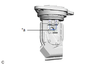
| (a) Perform a visual check for any foreign matter on the temperature sensor (thermistor) of the mass air flow meter shown in the illustration. OK: There is no foreign matter. If the result is not as specified, replace the mass air flow meter. |
|
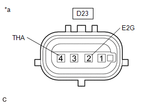
| (b) Measure the resistance according to the value(s) in the table below. Standard Resistance:
If the result is not as specified, replace the mass air flow meter. |
|
 Removal
REMOVAL CAUTION / NOTICE / HINT The necessary procedures (adjustment, calibration, initialization, or registration) that must be performed after parts are removed, installed, or replaced during the mass air flow meter removal/installation are shown below...
 Installation
INSTALLATION PROCEDURE 1. INSTALL MASS AIR FLOW METER (a) Install the mass air flow meter to the air cleaner cap sub-assembly with the 2 screws. NOTICE:
If the mass air flow meter has been struck or dropped, replace it...
Other information:
Toyota Yaris XP210 (2020-2026) Reapir and Service Manual: Components
COMPONENTS ILLUSTRATION *1 FRONT NO. 1 VENTILATOR SEAL *2 WATER GUARD PLATE RH *3 OUTER COWL TOP PANEL SUB-ASSEMBLY - - N*m (kgf*cm, ft.*lbf): Specified torque - - ILLUSTRATION *1 BRAKE MASTER CYLINDER O-RING *2 BRAKE MASTER CYLINDER SUB-ASSEMBLY *3 CONNECTOR *4 NO...
Toyota Yaris XP210 (2020-2026) Reapir and Service Manual: Front Passenger Side Power Window Auto Up / Down Function does not Operate with Front Passenger Side Power Window Switch
DESCRIPTION If the manual up and down functions operate normally but the auto up and down functions do not, the power window control system may be in fail-safe mode. If power window initialization has not been performed, the auto up and down functions will not operate...
Categories
- Manuals Home
- Toyota Yaris Owners Manual
- Toyota Yaris Service Manual
- Engine & Hybrid System
- Battery Monitor Module General Electrical Failure (P058A01)
- How to connect USB port/Auxiliary jack
- New on site
- Most important about car
Keys

To use the auxiliary key, press the knob and pull out the auxiliary key from the smart key.
