Toyota Yaris: Stop And Start System / Data List / Active Test
DATA LIST / ACTIVE TEST
DATA LIST
HINT:
Using the GTS to read the Data List allows the values or states of switches, sensors, actuators and other items to be read without removing any parts. This non-intrusive inspection can be very useful because intermittent conditions or signals may be discovered before parts or wiring is disturbed. Reading the Data List information early in troubleshooting is one way to save diagnostic time.
NOTICE:
In the table below, the values listed under "Normal Condition" are reference values. Do not depend solely on these reference values when deciding whether a part is faulty or not.
(a) According to the display on the GTS, read the Data List.
Powertrain > Stop and Start > Data List| Tester Display | Measurement Item | Range | Normal Condition | Diagnostic Note |
|---|---|---|---|---|
| Total Distance Traveled | Total distance traveled | Min.: 0 Max.: 1677215 | - | - |
| Total Distance Traveled - Unit | Unit of Total Distance Traveled | km / mile | - | - |
| Neutral Switch | Park/Neutral position switch assembly status | OFF / ON | ON: Shift lever in P or N OFF: Shift lever not in P or N | - |
| IG Switch | Push start switch assembly signal | OFF / ON | ON: Ignition switch ON | - |
| Stop Light SW (ECM) | Stop light switch assembly signal from ECM | OFF / ON | ON: Brake pedal depressed OFF: Brake pedal fully released | This is sent from the ECM. |
| Stop Light SW (ABS/VSC) | Stop light switch assembly signal from electronically controlled brake system | OFF / ON | ON: Brake pedal depressed OFF: Brake pedal fully released | This is sent from the skid control ECU (brake actuator assembly). |
| Driver Courtesy Switch Signal | Driver door courtesy switch signal | OFF / ON | ON: Driver side door open OFF: Driver side door closed | - |
| Hood Courtesy Switch | Hood courtesy switch signal | ON / OFF | ON: Engine hood closed OFF: Engine hood open | - |
| Stop&Start Cancel Switch | Stop and start system cancel switch (combination switch assembly) signal | OFF / ON | ON: Stop and start system cancel switch (combination switch assembly) pressed OFF: Stop and start system cancel switch (combination switch assembly) not pressed | - |
| Starter | Starter status | OFF / ON | ON: Cranking OFF: Not cranking | - |
| Engine Starter Signal | Starter signal status | OFF / ON | ON: Cranking OFF: Not cranking | This is sent from the ECM. |
| Driver Seat Belt Buckle Switch | Driver seat belt buckle switch status | Buckled / Not Buckled / Unfix / Abnormal | Buckled: Driver seat belt fastened Not Buckled: Driver seat belt not fastened | - |
| Engine Speed (ECM) | Engine speed signal from ECM via CAN communication | Min.: -25600 rpm Max.: 25599.21 rpm | 600 to 700 rpm: When idling after warm up, shift lever in N and no load | This is sent from the ECM. |
| Battery Current | Auxiliary battery current | Min.: -125 A Max.: 124.9961 A | - | - |
| Brake Boost Pressure | Brake booster pressure (absolute pressure) | Min.: -640 kPa(abs) (-4800 mmHg(abs), -189 in.Hg(abs)) Max.: 639.98 kPa(abs) (4800.25 mmHg(abs), 188.99 in.Hg(abs)) | Approx. 100 kPa (750 mmHg, 29.5 in.Hg): Ignition switch ON, brake pedal depressed several times (differs according to atmospheric pressure) | - |
| Brake Negative Pressure | Brake booster vacuum (negative pressure) | Min.: -640 kPa(gauge) (-4800 mmHg(gauge), -189 in.Hg(gauge)) Max.: 639.98 kPa(gauge) (4800.25 mmHg(gauge), 188.99 in.Hg(gauge)) | Approx. 0 kPa (0 mmHg, 0 in.Hg): Ignition switch ON, brake pedal depressed several times | This item cannot be checked if a malfunction occurs in communication with ECM. |
| Gradient of Road Surface | Degree of road gradient | Min.: -10.24 m/s2 Max.: 10.16 m/s2 | -1.4 to 1.4 m/s2: Vehicle stopped on level surface | - |
| Battery Fluid Temperature (Start) | Auxiliary battery fluid temperature at engine start | Min.: -40°C (-40°F) Max.: 215 °C (419 °F) | Differs according to auxiliary battery fluid temperature: Engine start | - |
| Battery Fluid Temperature | Estimated temperature inside auxiliary battery | Min.: -40°C (-40°F) Max.: 215 °C (419 °F) | Changes according to actual temperature: Driving after engine warmed up | - |
| Buzzer | Buzzer status | OFF / ON | ON: Buzzer on OFF: Buzzer does not sound | Refer to warning buzzer operation conditions. |
| Oil Pressure Warning Light Prohibit | Oil pressure warning status | Permit / Prohibit | Prohibit: During engine stop by stop and start control Permit: Not during engine stop by stop and start control | Engine stop and start ECU informs the combination meter assembly that the oil pressure warning does not come on during engine stop by stop and start control. |
| Stop&Start Cancel Light Code | Transmission code from the engine stop and start ECU to the combination meter assembly | 0 / 1 / 2 / 3 / 4 0: Off 1: Illuminated 2: Blinking 3: - 4: DTC output | 0: Stop and start cancel indicator off 1: Stop and start cancel indicator on | Stop and start cancel indicator on/blinking/off request sent to combination meter assembly. |
| Stop&Start Operating Permission (Neutral Switch) | Permission of stop and start control based on the park/neutral position switch assembly conditions | NG / OK | - | - |
| Stop&Start Operating Permission (Vehicle Speed) | Permission of stop and start control based on the vehicle speed conditions | NG / OK | OK: Vehicle stopped | - |
| Stop&Start Precondition | Permission of stop and start control with all preconditions met | OFF / ON | ON: Preconditions for stop and start control have been met | Condition of permission or prohibition for terms listed below. (ECM 1, ECM 2, ABS/VSC, Elapsed Time After IG-ON, DTC, A/C, Idling Stop Performance Waiting Time, After Running, Engine Hood Closed, Driver Door Closed, Cancel Switch, AT/CVT, AT/CVT 2, Interval For Starter, Key Operation, Driver Side Buckle SW, Ambient Temperature) For details on the preconditions, refer to System Description. |
| Stop&Start Precondition 2 | Permission of stop and start control with all preconditions met | OFF / ON | ON: Preconditions for stop and start control have been met | Condition of permission or prohibition for terms listed below. (Idling, Road Surface Gradient, No Shift Operation, Brake Negative Pressure, Steering, Oil Pump, Starter Check Complete) |
| Hill Judging | Hill judgment | Not Hill / Hill | - | - |
| IG-ON State Before Starting | Permission of stop and start control based on the vehicle speed since ignition switch turned to ON | OFF / ON | - | - |
| Engine Start Request (Brake Negative Pressure Low) | Engine start request due to low brake booster vacuum | OFF / ON | ON: Brake booster vacuum insufficient while engine stopped by stop and start control |
|
| Engine Start Request (ABS Vehicle Speed) | Engine start request based on vehicle speed signal from the electronically controlled brake system | OFF / ON | ON: Engine start requested due to speed signal while the engine is stopped by stop and start | Engine start request based on the speed sensor signal |
| Engine Start Request (Steering) | Engine start request by the power steering system | OFF / ON | ON: Engine start requested due to operation of power steering system | - |
| Engine Start Request (Cancel SW) | Engine start request by stop and start system cancel switch (combination switch assembly) | OFF / ON | ON: Engine start requested due to operation of the stop and start system cancel switch (combination switch assembly) while the engine is stopped by stop and start control | - |
| Engine Start Request (IG Switch) | Engine start request due to push start switch assembly operation | OFF / ON | ON: Engine started using push start switch assembly while engine stopped by stop and start control | - |
| Engine Start Request (A/C) | Engine start request from air conditioning system | OFF / ON | ON: Engine start requested by air conditioning system | - |
| Engine Start Request (Battery Condition) | Engine start request based on auxiliary battery performance | OFF / ON | ON: Engine start requested due to low auxiliary battery voltage while the engine is stopped by stop and start control | - |
| Engine Start Request (ECM) | Engine start request from ECM | OFF / ON | ON: Engine start requested by ECM | - |
| Engine Start Request (Detect DTC) | Engine start request due to output of DTCs | OFF / ON | ON: Engine start requested due to output of stop and start system DTCs | - |
| Engine Start Request (Shift P Position and Brake) | Engine start request due to brake being depressed when the shift lever in P and the engine is stopped due to stop and start control | OFF / ON | ON: Engine start requested | - |
| Engine Start Request (4WD and Rear Differential Lock) | Engine start request by AWD and rear differential lock*1 | OFF / ON | ON: Vehicle is switched to AWD or rear differential is locked while the engine is stopped due to stop and start control | - |
| Engine Start Request (ACC) | Engine start request by dynamic radar cruise control system*1 | OFF / ON | ON: Engine start request based on dynamic radar cruise control system | Unused |
| Engine Stall History during Stop&Start (Hood Open) | History of engine stall due to the engine hood being opened with shift lever in D while the engine is stopped by stop and start control | No / Yes | No: No history | - |
| Engine Stall History during Stop&Start (Collision or Battery Voltage Low) | History of engine stall due to a collision or low auxiliary battery voltage when stop and start control operating | No / Yes | No: No history | - |
| Engine Stall History during Engine Starting (Collision) | History of engine stall due to a collision while engine stopped by stop and start control | No / Yes | No: No history | - |
| Engine Start Fail | History of engine restart failure while engine stopped by stop and start control | No / Yes | No: No history | - |
| Starter Operation # | Number of starter operations (count record) | Min.: 0 times Max.: 16777215 times | - | - |
| Number of Engine Starts (IG-ON) | The number of starter operations by push start switch assembly operation | Min.: 0 times Max.: 16777215 times | - | - |
| Number of Engine Starts (Stop & Start) | The number of starter operations by stop and start control | Min.: 0 times Max.: 16777215 times | - | - |
| Deceleration Sensor Offset Value | Deceleration sensor offset value | Min.: -1176.04 m/s2 Max.: 1176 m/s2 | -0.9 to 0.9 m/s2: After deceleration sensor zero point learning completion | Unused |
| Deceleration Sensor Calibration | Deceleration sensor calibration status | Incomplete / Running / Complete / Err1 / Err2 / Err3 | Complete: After deceleration sensor zero point learning completion | Unused |
| Stop&Start of Engine State | Stop and start control status | IG / Run / Stop Request / Stop / Restart |
| - |
| Idling Stop Rate | Rate of the idling stop time to the entire ignition switch to ON time of this trip | Min.: 0% Max.: 255% | - | - |
| Total Idling Stop Rate | Rate of the overall idling stop time to the overall ignition switch to ON time | Min.: 0% Max.: 255% | - | - |
| Stop & Start A/C Mode | Selected air conditioning mode | Undefined / Normal / Stop&Start Prioritized / A/C Prioritized | - | - |
| Integrated Current | Auxiliary battery integrated current | Min.: -268434.456 A-sec Max.: 268435.4558 A-sec | Differs according to vehicle condition (charge/discharge conditions) | Refer to "Regarding Auxiliary Battery Integrated Current" for details.*1 |
| Status of Battery Charge Control | Auxiliary battery charge control status | Charge Control Coordination Mode / Stop and Start Standalone Mode / Refresh Charge Mode / Stop and Start Restriction Mode / Temperature High/Low Mode / Abnormal Mode / Auxiliary battery Condition Judgment Mode / Low Temperature Mode | - | - |
| Cranking Time | Engine cranking time | Min.: 0 msec Max.: 134215.68 msec | 300 to 3000 msec: Duration of starter operation by stop and start control | - |
| Minimum Voltage (Cranking) | Minimum voltage when cranking engine | Min.: -327.68 V Max.: 327.67 V | 6 to 11 V | Lowest auxiliary battery voltage measured after the starter starts operating. |
| Minimum Voltage (Starter Solenoid Engagement) | Minimum voltage when starter begins operation | Min.: -327.68 V Max.: 327.67 V | 6 to 11 V | Minimum auxiliary battery voltage while the starter starts operating. |
| Starter Type | Starter assembly type | Other than Tandem Starter / Tandem Starter | Tandem Starter | Unused |
| State of BBC | Backup boost converter status | Cycle Err / Overvoltage / Overload / Normal / Low Vol / Duty Err / Stop&Start Sensor Electric Supply Low / Stop&Start CPU Malfunction / BBC Overcurrent / Stop&Start Starter Overcurrent / Stop&Start Reduced Voltage Reset | Normal: Backup boost converter operating normally |
|
| Stop&Start Operating Permission (Idling) | Permission of stop and start control based on the engine idle conditions | NG / OK | OK: Engine idling (engine speed below 1250 rpm) without accelerator pedal being depressed | - |
| Stop&Start Operating Permission (Brake Negative Pressure) | Permission of stop and start control based on the brake booster vacuum conditions | NG / OK | OK: Brake vacuum is 31.5 kPa to 56.8 kPa (236 mmHg, 9.3 in.Hg to 426 mmHg, 16.8 in.Hg) or more for 1 second or longer | - |
| Stop&Start Operating Permission (After Running) | Permission of stop and start control based on the initial trip conditions after the ignition switch is turned to ON | NG / OK | OK: Vehicle has been driven at 7 km/h (4 mph) or more | OK is displayed after the initial trip until the ignition switch is turned off. |
| Stop&Start Operating Permission (Steering) | Permission of stop and start control by the power steering ECU | NG / OK | OK: Power steering system is operating normally | - |
| Stop&Start Operating Permission (Engine Hood Closed) | Permission of stop and start control based on the engine hood open/close conditions | NG / OK | OK: Engine hood closed | - |
| Stop&Start Operating Permission (Cancel Switch) | Permission of stop and start control based on the stop and start system cancel switch (combination switch assembly) operation | NG / OK | OK: Stop and start control is permitted (stop and start cancel indicator is not illuminated) | - |
| Stop&Start Operating Permission (Driver Side Buckle SW) | Permission of stop and start control based on the driver seat belt condition | NG / OK | OK: The driver side buckle switch is fastened | - |
| Stop&Start Operating Permission (Driver Door Closed) | Permission of stop and start control based on the driver door open/close conditions | NG / OK | OK: Driver door closed | - |
| Stop&Start Operating Permission (Key Operation) | Permission of stop and start control based on the push start switch assembly operation | NG / OK | OK: Push start switch assembly not operated | - |
| Stop&Start Operating Permission (Interval For Starter) | Permission of stop and start control based on the conditions after engine restart | NG / OK | OK: 4 minutes or less have elapsed after engine restarted | - |
| Stop&Start Operating Permission (Starter Check Complete) | Permission of stop and start control based on the starter circuit self-check result | NG / OK | OK: Stop and start control enabled (starter circuit normal) | When the engine stop and start ECU is abnormal, the starter drive circuit is judged to be abnormal, and NG is displayed |
| Stop&Start Operating Permission (A/C) | Permission of stop and start control based on the air conditioning conditions | NG / OK | OK: Air conditioning conditions met | - |
| Stop&Start Operating Permission (Power Management) | Permission of stop and start control based on the auxiliary battery conditions | NG / OK | OK: Stop and start control permitted based on auxiliary battery conditions, or Active Test (forced permission) performed | - |
| Stop&Start Operating Permission (ECM 2) | Permission of stop and start control by SFI system | NG / OK | OK: Stop and start control enabled (SFI system is normal) | This is sent from the ECM through CAN communication. |
| Stop&Start Operating Permission (ECM 1) | Permission of stop and start control by the ECM | NG / OK | OK: Stop and start control enabled (SFI system is normal) | - |
| Stop&Start Operating Permission (Elapsed Time After IG-ON) | Permission of stop and start control based on time elapsed since ignition switch turned to ON | NG / OK | OK: Permitted NG: Not permitted | - |
| Stop&Start Operating Permission (Idling Stop Performance Waiting Time) | Permission of stop and start control to be operated 2 or more times during a stop based on stop time | NG / OK | OK: Permitted NG: Not permitted | - |
| Stop&Start Operating Permission (Ambient Temperature) | Permission of stop and start control based on the air conditioning conditions | NG / OK | OK: Ambient temperature -5°C (23°F) or higher | - |
| Stop&Start Operating Permission (Road Surface Gradient) | Permission of stop and start control based on the road grade conditions | NG / OK | OK: Vehicle stopped on level road (not steep grade) | - |
| Stop&Start Operating Permission (DTC) | Permission of stop and start control based on the DTC output conditions | NG / OK | OK: DTC not output | - |
| Stop&Start Operating Permission (Minimum Voltage (Starter Solenoid Engagement)) | Permission of stop and start control based on minimum voltage during starter solenoid engagement | NG / OK | OK: Minimum voltage when starter begins operation is equal to the threshold or higher | If both Minimum Voltage (Starter Solenoid Engagement) condition and Minimum Voltage (Cranking) condition are OK, stop and start control is permitted. |
| Stop&Start Operating Permission (Minimum Voltage (Cranking)) | Permission of stop and start control based on minimum voltage during cranking | NG / OK | OK: Minimum voltage when cranking is equal to the threshold or higher | If both Minimum Voltage (Starter Solenoid Engagement) condition and Minimum Voltage (Cranking) condition are OK, stop and start control is permitted. |
| Stop&Start Operating Permission (4WD and Rear Differential Lock) | Permission of stop and start control by the AWD and rear differential lock*1 | NG / OK | OK: Permitted NG: When in AWD or with the rear differential in the lock condition | Unused |
| Stop&Start Operating Permission (ACC) | Permission of stop and start control by the dynamic radar cruise control system*1 | NG / OK | - | Unused |
| EPS Load | Electric power steering current | Min.: -327.68 A Max.: 327.67 A | Approx. 0 A: Electric power steering assist not activated | - |
| Steering Angle | Steering angle | Min.: -49152 deg Max.: 49150.5 deg | - | - |
| Steering Angle Velocity | Steering wheel turning speed | Min.: -32768 deg/s Max.: 32767 deg/s | - | - |
| Engine Stop Request | Engine stop request | OFF / ON | ON: During engine stop by stop and start control OFF: Not during engine stop by stop and start control | ON is displayed when fuel-cut is performed by stop and start control, engine start is not requested, or starter is forced to operate. |
| Stop&Start Cancel | Stop and start system cancel status | Not Cancel / Cancel | Cancel: Stop and start system cancel switch (combination switch assembly) depressed | - |
| Auto A/C | Availability of air conditioning system on vehicle | Without / With | With: Equipped with air conditioning system Without: Not equipped with air conditioning system | Air conditioning information needs to be registered after engine stop and start ECU replacement. |
| Running History | Vehicle driving record | OFF / ON | ON: After running | Turns OFF when the engine is stopped by stop and start control. |
| Wheel Speed Malfunction | Wheel speed sensor malfunction status | OFF / ON | OFF: Input value from speed sensor is normal | ON remains displayed when any input values from the wheel speed sensors are abnormal. |
| EPS Assist Current Available | Whether the power steering assist current value is available | Avail / Not Avail | - | Avail is also displayed when the power steering system is operating. |
| Fuel Cut Signal | Fuel cut signal | OFF / ON | ON: Fuel cut operating | - |
| Idle | Engine idling status | OFF / ON | ON: Accelerator pedal fully released OFF: Accelerator pedal depressed | This is sent from the ECM. |
| Engine Start (IG SW) | Engine start by push start switch assembly operation | OFF / ON | ON: Engine start by push start switch assembly operation OFF: Except engine start by push start switch assembly operation | Indicates starter operation by operation of the push start switch assembly. |
| Engine Start Request (Courtesy SW or Buckle SW) | Engine start request by courtesy switch (for driver side) or driver side buckle switch | OFF / ON | ON: Engine start requested due to operation of the courtesy switch (for driver side) or driver side buckle switch while the engine is stopped by stop and start control | - |
| Stop&Start Operating Permission (Integrated Current) | Permission of stop and start control based on the integrated current value conditions | NG / OK | OK: Integrated current value is equal to the threshold or more | The status depends on the value of "Integrated Current", and the OK/NG threshold differs according to the auxiliary battery fluid temperature. Refer to "Regarding Auxiliary Battery Integrated Current" below for details.*3 |
| Stop&Start Operating Prohibition (Jump Start) | Prohibition of stop and start control based on the jump start conditions | Permit / Prohibit | Permit: Except for jump start conditions | When Prohibit is displayed, stop and start control will be prohibited until the ignition switch is turned off. Jump start conditions: Engine started with the engine hood and back door (for 3 Door) open and the ignition switch turned START |
| Deceleration Sensor Output Stuck | Deceleration sensor output stuck | Normal / Abnormal | Normal: Deceleration sensor output normal | Unused |
| ABS Running | Operating condition of the electronically controlled brake system | OFF / ON | ON: Electronically controlled brake system operating | - |
| Engine Type Information | Information on the engine type from the SFI system | Avail / Not Avail | Avail: Information of engine type received from ECM through CAN communication | Not Avail is displayed if improper engine type information is received from the ECM via CAN communication. |
| Steering Angle Sensor Malfunction | Steering sensor malfunction | OFF / ON | OFF: Normal | - |
| Steering Angle Sensor Circuit Open (+B) | Steering sensor +B circuit malfunction | OFF / ON | OFF: Normal | - |
| Steering Angle Sensor Abnormal Value | Steering sensor value malfunction | OFF / ON | OFF: Normal | - |
| Steering Torque Sensor Malfunction | Steering torque sensor status | OFF / ON | OFF: Steering torque sensor normal | - |
| Battery Type | Set auxiliary battery type | Specified / Other | Specified: Specified auxiliary battery Other: Non-specified auxiliary battery | - |
| Steering Wheel Torque | Steering wheel torque | Min.: -327.68 Nm Max.: 327.67 Nm | - | Turned right: Negative value Turned left: Positive value |
| Air Suspension Available | Availability of air suspension system on vehicle | No / Yes | No | Unused |
| Welcab Available | Availability of side lift up seat system on vehicle | No / Yes | No | Unused |
| External BBC Available | Availability of external backup boost converter (eco run vehicle converter assembly) on vehicle | No / Yes | Yes: External backup boost converter (eco run vehicle converter assembly) equipped No: External backup boost converter (eco run vehicle converter assembly) not equipped | - |
| Brake Hold Function Available | Availability of brake hold function on vehicle | No / Yes | Yes: Equipped No: Not equipped | - |
| Steering Angle Sensor Available | Availability of steering sensor on vehicle | No / Yes | Yes: Equipped No: Not equipped | - |
| PCS Available | Availability of pre-collision system on vehicle | No / Yes | Yes: Equipped No: Not equipped | - |
| Communication Method of Brake Boost Sensor | Method of communication with vacuum sensor assembly | Not CAN / CAN | Not CAN: Vacuum sensor signal not received via CAN communication | CAN: Vacuum sensor signal received via CAN communication |
| IPA Available | Whether the vehicle is equipped with the intelligent parking assist function | No / Yes | No | Unused |
| Cancel Switch (Multi-display) Available | Whether the vehicle is equipped with an stop and start system cancel switch (combination switch assembly) | No / Yes | No: A stop and start system cancel switch (combination switch assembly) is not available Yes: A stop and start system cancel switch (combination switch assembly) is available | - |
| ACC Available | Availability of dynamic radar cruise control system on vehicle*1 | No / Yes | Yes: Equipped No: Not equipped | Unused |
| ACC Operation State | Dynamic radar cruise control operating condition*1 | OFF / ON | ON: Operating OFF: Not operating | Unused |
| Number of Stop&Start Operating Prohibition (Elapsed Time After IG-ON) | Number of times stop and start control prohibited due to time elapsed since ignition switch turned to ON | Min.: 0 times Max.: 65535 times | - | - |
| Number of Stop&Start Operating Prohibition (DTC) | Number of stop and start control prohibitions due to DTC output | Min.: 0 times Max.: 65535 times | - | - |
| Number of Stop&Start Operating Prohibition (Brake Negative Pressure) | Number of stop and start control prohibitions due to brake negative pressure condition | Min.: 0 times Max.: 65535 times | - | - |
| Number of Stop&Start Operating Prohibition (Interval) | Number of stop and start control prohibitions due to periodic control prohibition after engine stop | Min.: 0 times Max.: 65535 times | - | - |
| Number of Stop&Start Operating Prohibition (Driver Door Closed) | Number of stop and start control prohibitions due to open driver door | Min.: 0 times Max.: 4294967295 times | - | - |
| Number of Stop&Start Operating Prohibition (Engine Hood Closed) | Number of stop and start control prohibitions due to open engine hood | Min.: 0 times Max.: 4294967295 times | - | - |
| Number of Stop&Start Operating Prohibition (A/C) | Number of stop and start control prohibitions due to air conditioning condition | Min.: 0 times Max.: 4294967295 times | - | - |
| Number of Stop&Start Operating Prohibition (After Running) | Number of stop and start control prohibitions based on the initial trip conditions | Min.: 0 times Max.: 65535 times | - | - |
| Number of Stop&Start Operating Prohibition (Power Management) | Number of stop and start control prohibitions due to auxiliary battery condition | Min.: 0 times Max.: 4294967295 times | - | - |
| Number of Stop&Start Operating Prohibition (Interval For Starter) | Number of stop and start control prohibitions due to starter fail-safe operation | Min.: 0 times Max.: 65535 times | - | - |
| Number of Stop&Start Operating Prohibition (Cancel Switch) | Number of stop and start control prohibitions due to stop and start system cancel switch (combination switch assembly) operation | Min.: 0 times Max.: 65535 times | - | - |
| Number of Stop&Start Operating Prohibition (Idling) | Number of stop and start control prohibitions due to idling condition | Min.: 0 times Max.: 65535 times | - | - |
| Number of Stop&Start Operating Prohibition (Road Surface Gradient) | Number of stop and start control prohibitions due to road surface gradient condition | Min.: 0 times Max.: 4294967295 times | - | - |
| Number of Stop&Start Operating Prohibition (Steering) | Number of stop and start control prohibitions due to power steering system condition | Min.: 0 times Max.: 65535 times | - | - |
| Number of Stop&Start Operating Prohibition (Key Operation) | Number of stop and start control prohibitions due to push start switch assembly operation | Min.: 0 times Max.: 65535 times | - | - |
| Number of Stop&Start Operating Prohibition (Starter Check Complete) | Number of stop and start control prohibitions due to incomplete starter circuit check | Min.: 0 times Max.: 65535 times | - | - |
| Number of Stop&Start Operating Prohibition (Driver Side Buckle SW) | Number of stop and start control prohibitions due to unfastened driver seat belt | Min.: 0 times Max.: 65535 times | - | - |
| Number of Stop&Start Operating Prohibition (Ambient Temperature) | Number of stop and start control prohibitions due to ambient temperature condition | Min.: 0 times Max.: 65535 times | - | - |
| Number of Stop&Start Operating Prohibition (ECM 2) | Number of stop and start control prohibitions due to SFI system | Min.: 0 times Max.: 65535 times | - | - |
| Number of Stop&Start Operating Prohibition (Start Minimum Voltage) | Number of stop and start control prohibitions due to auxiliary battery condition | Min.: 0 times Max.: 65535 times | - | - |
| Number of Stop&Start Operating Prohibition (Battery Current) | Number of stop and start control prohibitions due to auxiliary battery condition | Min.: 0 times Max.: 4294967295 times | - | Unused |
| Number of Stop&Start Operating Prohibition (Integrated Current) | Number of stop and start control prohibitions due to auxiliary battery condition | Min.: 0 times Max.: 4294967295 times | - | - |
| Number of Stop&Start Operating Prohibition (Jump Start) | Number of stop and start control prohibitions due to jump start | Min.: 0 times Max.: 65535 times | - | - |
| Number of Stop&Start Operating Prohibition (Deceleration Sensor Abnormal) | Number of stop and start control prohibitions due to deceleration sensor malfunction | Min.: 0 times Max.: 65535 times | - | Unused |
| Number of Stop&Start Operating Prohibition (Engine F/C) | Number of stop and start control prohibitions due to fuel-cut | Min.: 0 times Max.: 65535 times | - | - |
| Number of Stop&Start Operating Prohibition (Abnormal Wheel Speed Sensor Inputs) | Number of stop and start control prohibitions due to abnormal vehicle speed signal input | Min.: 0 times Max.: 65535 times | - | - |
| Number of Stop&Start Operating Prohibition (Total Number of Engine Starts) | Number of times stop and start control prohibited due to total number times engine started | Min.: 0 times Max.: 65535 times | - | - |
| Number of Stop&Start Operating Prohibition (Accelerator) | Number of stop and start control prohibitions due to accelerator pedal operation | Min.: 0 times Max.: 65535 times | - | - |
| Number of Stop&Start Operating Prohibition (IPA) | Number of stop and start control prohibitions due to intelligent parking assist system | Min.: 0 times Max.: 65535 times | - | Unused |
| Number of Stop&Start Operating Prohibition (4WD and Rear Differential Lock) | Number of stop and start control prohibitions due to AWD and rear differential lock*1 | Min.: 0 times Max.: 65535 times | - | Unused |
| Number of Engine Start Request (Brake Negative Pressure Insufficient) | Number of engine start requests due to insufficient brake booster vacuum | Min.: 0 times Max.: 65535 times | - | - |
| Number of Engine Start Request (IG Switch) | Number of engine start requests due to push start switch assembly operation | Min.: 0 times Max.: 65535 times | - | - |
| Number of Engine Start Request (ECM) | Number of engine start requests from SFI system | Min.: 0 times Max.: 65535 times | - | - |
| Number of Engine Start Request (A/C) | Number of engine start requests from air conditioning system | Min.: 0 times Max.: 65535 times | - | - |
| Number of Engine Start Request (Steering) | Number of engine start requests due to steering operation | Min.: 0 times Max.: 65535 times | - | - |
| Number of Engine Start Request (Detect DTC) | Number of engine start requests due to DTC output | Min.: 0 times Max.: 65535 times | - | - |
| Number of Engine Start Request (Battery Condition) | Number of engine start requests due to low auxiliary battery performance | Min.: 0 times Max.: 65535 times | - | - |
| Number of Engine Start Request (Cancel SW) | Number of engine start requests due to stop and start system cancel switch (combination switch assembly) operation | Min.: 0 times Max.: 65535 times | - | - |
| Number of Engine Start Request (ABS Vehicle Speed) | Number of engine start requests due to electronically controlled brake system vehicle speed signal input | Min.: 0 times Max.: 65535 times | - | - |
| Number of Engine Start Request (Driver Side Buckle) | Number of engine start requests due to driver seat belt condition | Min.: 0 times Max.: 65535 times | - | - |
| Number of Engine Start Request (Driver Door) | Number of engine start requests due to driver door condition | Min.: 0 times Max.: 65535 times | - | - |
| Number of Engine Start Request (4WD and Rear Differential Lock) | Number of engine start requests due to AWD and rear differential lock*1 | Min.: 0 times Max.: 65535 times | - | Unused |
| Number of Stop&Start Canceled (Hood Open) | Number of times stop and start system canceled due to engine hood being opened | Min.: 0 times Max.: 255 times | - | - |
| Number of Engine Stall (Restart Failed) | Number of times engine stalled due to engine restart failure while engine stopped by stop and start control | Min.: 0 times Max.: 255 times | - | - |
| Number of Stop&Start Canceled (Reduced Voltage) | Number of times stop and start system canceled due to low auxiliary battery voltage | Min.: 0 times Max.: 255 times | - | - |
| Number of Stop&Start Canceled (CPU Malfunction) | Number of times stop and start system canceled due to engine stop and start ECU malfunction | Min.: 0 times Max.: 255 times | - | - |
| Coolant Temperature | Engine coolant temperature | Min.: -40°C (-40°F) Max.: 215 °C (419 °F) | 40 to 100°C (104 to 212°F): After warming up | This is sent from the ECM. |
| Engine Speed | Engine speed | Min.: 0 rpm Max.: 16383 rpm | 600 to 700 rpm: Idling (shift lever in N, engine warmed up and A/C off) | - |
| Vehicle Speed | Vehicle speed | Min.: 0 km/h Max.: 255 km/h (158 mph) | Actual vehicle speed | - |
| Atmospheric Pressure | Atmospheric pressure (calculated value) | Min.: 0 kPa(abs) (0 kgf/cm2(abs), 0 psi(abs)) Max.: 255 kPa(abs) (2.6 kgf/cm2(abs), 37 psi(abs)) | Approx. 100 kPa(abs) (1.0 kgf/cm2(abs), 15 psi(abs)): Ignition switch ON (close to actual atmospheric pressure) | ECM calculated value |
| Battery Voltage | Auxiliary battery voltage | Min.: 0 V Max.: 65.5 V | 9 to 14 V: Idling | - |
| Ambient Temperature | Ambient temperature | Min.: -40°C (-40°F) Max.: 215 °C (419 °F) | Close to ambient temperature | - |
| Stop&Start Buzzer | Buzzer status | OFF / ON | ON: Active Test [Stop&Start Buzzer] ON | Active Test [Stop&Start Buzzer] support data. |
| Engine Start Request (Clutch Pedal ON) | Engine start request by the clutch pedal | OFF / ON | ON: Clutch pedal is depressed | - |
| Engine Start Request (Clutch Lower Switch ON) | Engine start request by the clutch switch assembly | OFF / ON | ON: Clutch pedal is fully depressed | - |
| Engine Start Request (IPA) | Engine start request from intelligent parking assist system | OFF / ON | ON: Engine start requested by intelligent parking assist system | Unused |
| Stop&Start Operating Permission (Manual Start) | Permission of stop and start control based on the manual start conditions | NG / OK | - | - |
| Stop&Start Operating Permission (Clutch) | Stop and start control permission condition (clutch) | NG / OK | ON: Clutch pedal is not depressed | - |
| Stop&Start Operating Permission (Shift Position) | Stop and start control permission condition (shift position) | NG / OK | - | - |
| Stop&Start Operating Permission (IPA) | Permission of stop and start control by Simple Intelligent Parking Assist System | NG / OK | - | Unused |
| ECB Available | Availability of electronically controlled brake system (w/o Vacuum Brake Booster) on vehicle | No / Yes | No | Unused |
| Clutch Lower Switch | Clutch switch assembly signal | OFF / ON | OFF: Clutch pedal released ON: Clutch pedal fully depressed | - |
| N Position Switch Signal Voltage | Neutral position switch signal voltage | Min.: 0 V Max.: 4.99 V | - | - |
| Number of Engine Starts (Clutch Released) | The number of starter operations without clutch pedal being depressed | Min.: 0 Max.: 4294967295 | - | - |
| Number of Engine Starts (Clutch Half-Depressed) | The number of starter operations with clutch pedal depressed halfway | Min.: 0 Max.: 4294967295 | - | - |
| Wrong Operation (Start) | Wrong operation for engine start | OFF / ON | OFF | Unused |
| Manual Start History during Stop&Start | Vehicle started manually while stop and start was operating | OFF / ON | ||
| N/Clutch Lower Switch Malfunction | Clutch switch assembly | ON / OFF | - | - |
| N/Clutch Upper Switch Malfunction | Clutch switch assembly (for upper) | ON / OFF | - | - |
| Stop&Start Operating Prohibition (Manual Start for the First Time) | Prohibition of stop and start control based on the manual start conditions | Permit / Prohibit | Permit: Except for manual start conditions |
|
| Clutch Status | Clutch switch assembly status | Half Clutch / Disconnect / Connect / Unknown | - | - |
| Clutch Stroke Sensor Malfunction | Clutch stroke sensor malfunction | ON / OFF | OFF: Clutch stroke sensor is normal | Unused |
| Number of Stop&Start Operating Prohibition (No Shift Operation (MT)) | Number of stop and start control prohibitions based on shift lever position condition | Min.: 0 Max.: 65535 | - | - |
| Number of Stop&Start Operating Prohibition (Shift Operation without Clutch Pedal Operation) | Number of stop and start prohibitions (shift lever operated without clutch pedal depressed) | Min.: 0 Max.: 65535 | - | - |
| Number of Stop&Start Operating Prohibition (Manual Start for the First Time) | Number of stop and start control prohibitions due to manual start condition | Min.: 0 Max.: 65535 | - | - |
| Number of Stop&Start Operating Prohibition (Manual Start during Stop&Start) | Number of stop and start control prohibitions due to manual start condition | Min.: 0 Max.: 65535 | - | - |
| Number of Stop&Start Operating Prohibition (Neutral Switch Malfunction) | Number of stop and start prohibitions (neutral switch malfunction) | Min.: 0 Max.: 65535 | - | - |
| Number of Engine Start Request (Clutch Release) | Number of engine start requests from clutch switch assembly | Min.: 0 Max.: 65535 | - | - |
| Number of Engine Start Request Prohibition (Wrong Shift Lever Operation) | Number of engine start requests due to wrong shift lever operation | Min.: 0 Max.: 65535 | - | - |
In the stop and start system, the engine stop and start ECU switches the system control mode (stop and start control permitted/prohibited) based on the auxiliary battery condition (charge/discharge condition) to protect the auxiliary battery and to ensure stable engine restarting performance.
The auxiliary battery charge/discharge condition is determined from the integrated current value calculated from the auxiliary battery sensor signal. The integrated current value is obtained by multiplying the current (Ampere) detected from the auxiliary battery sensor by the time (seconds), and it is expressed in a unit A-sec.
HINT:
Example: Integrated current of -3110 A-sec corresponds to a load where current of 10 A flows out from the auxiliary battery for 311 seconds.
The integrated current value can be read by checking the Data List item "Integrated Current" using GTS. The item "Stop&Start Operating Permission (Integrated Current)" shows the permission status of stop and start control (OK or NG) and is judged from the "Integrated Current" value.
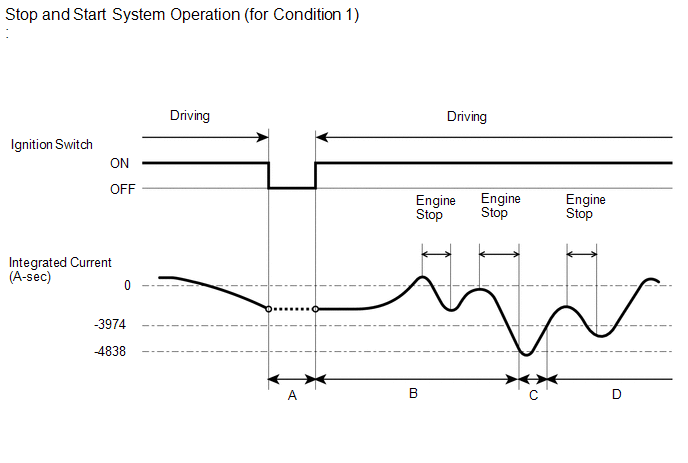
Negative integrated current represents auxiliary battery discharge, and positive represents auxiliary battery charge. In other words, the "Integrated Current" value of the Data List item will decrease from the present value when the auxiliary battery is discharged, and the value will increase when the auxiliary battery is charged.
The engine stop and start ECU determines the amount of power available based on the integrated current value, and it prohibits stop and start control if the value is below the threshold, because the auxiliary battery might not be able to start the engine. The threshold varies according to the auxiliary battery fluid temperature.
Integrated Current Condition 1:When "Status of Auxiliary Battery Charge Control" is Charge Control Coordination Mode, Stop and Start Standalone Mode or Low Temperature Mode:
-
Phase A (previous trip integrated current storage):
When the ignition switch is turned off, the integrated current value is recorded in the ECU memory. The value is carried over to the next trip.
-
Phase B (stop and start control permitted):
Stop and start control is permitted to stop the engine until the integrated current reaches -4838 A-sec or less.
-
Phase C (charging):
When the integrated current has dropped to -4838 A-sec or less, stop and start control is prohibited from stopping the engine until the current reaches -3974 A-sec.
-
Phase D (stop and start control permitted):
Stop and start control is permitted to stop the engine until the integrated current reaches -4838 A-sec or less.
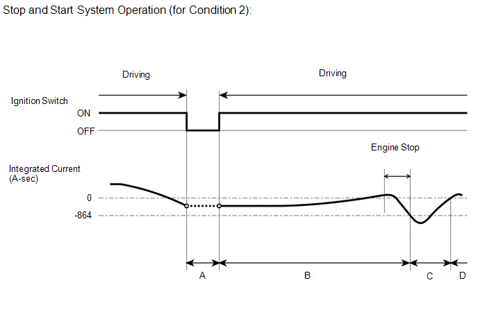
When "Status of Auxiliary Battery Charge Control" is Stop and Start Restriction Mode or Temperature High/Low Mode:
-
Phase A (previous trip integrated current storage):
When the ignition switch is turned off, the integrated current value is recorded in the ECU memory. The value is carried over to the next trip.
-
Phase B (stop and start control permitted):
Stop and start control is permitted to stop the engine until the integrated current reaches -864 A-sec or less.
-
Phase C (charging):
When the integrated current has dropped to -864 A-sec or less, stop and start control is prohibited from stopping the engine until the current reaches 0 A-sec.
-
Phase D (stop and start control permitted):
Stop and start control is permitted to stop the engine until the integrated current reaches -864 A-sec or less.
HINT:
- If the battery is deteriorated, the internal resistance has also increased and the stop and start rate becomes lower. (The total of idling time while the vehicle is stopped increases.)
- When troubleshooting, if the malfunction cannot be identified, the battery might be deteriorated.
ACTIVE TEST
HINT:
Using the GTS to perform Active Tests allows relays, actuators and other items to be operated without removing any parts. This non-intrusive functional inspection can be very useful because intermittent operation may be discovered before parts or wiring is disturbed. Performing Active Tests early in troubleshooting is one way to save diagnostic time. Data List information can be displayed while performing Active Tests.
(a) Perform the Active Test by referring to the table below.
HINT:
Even if stop and start control is prohibited due to the condition of any of the systems listed above, performing the Active Tests allows stop and start control to be performed.
Powertrain > Stop and Start > Active Test| Tester Display | Measurement Item | Control Range | Diagnostic Note |
|---|---|---|---|
| Stop&Start Buzzer | Buzzer activation | ON / OFF | - |
| Stop&Start Permit Cond (Engine) | When stop by stop and start control is prohibited, prohibition of control based on the SFI system conditions can be disabled/enabled. | ON / OFF | - |
| Stop&Start Permit Cond (Battery) | When stop by stop and start control is prohibited, prohibition of control based on the auxiliary battery conditions can be disabled/enabled. | ON / OFF | - |
| Stop&Start Permit Cond (A/C) | When stop by stop and start control is prohibited, prohibition of control based on the air conditioning conditions can be disabled/enabled. | ON / OFF | - |
| Stop&Start Precondition2 (Control) | Stop and start control can be permitted/prohibited based on precondition 2 | ON / OFF | Condition of permission or prohibition for terms listed below. (Idling, Road Surface Gradient, No Shift Operation, Brake Negative Pressure, Steering, Oil Pump, Starter Check Complete) |
| Starter(Hood Close) | Starter activation | ON / OFF | Perform this test when the following conditions are met:
NOTICE:
|
| Pinion Gear Plunger(Hood Close) | Starter pinion gear can be moved inward/outward | ON / OFF | Perform this test when the following conditions are met:
NOTICE:
|
| Starter Motor Drive Magnet Switch(Hood Close) | Starter motor can be turned on/off | ON / OFF | Perform this test when the following conditions are met:
NOTICE:
|
 Fail-safe Chart
FAIL-SAFE CHART If any of the following DTCs are stored, the engine stop and start ECU enters fail-safe mode to preserve vehicle operability. DTC Component Fail-safe Operation Fail-safe Deactivation Condition P033562 Open in engine speed signal circuit
Stop and start control is prohibited
Engine is automatically restarted if a DTC is stored while the engine is stopped by stop and start control
All of the following conditions are met for 10 seconds:
Normal communication with ECM
Engine speed 500 rpm or higher
Engine speed (communication signal) 500 rpm or higher
Difference between engine speed from pulse signal and engine speed from communication signal is less than 100 rpm
P055500 P05552A
Vacuum sensor assembly
Brake booster assembly
Vacuum hose (brake booster hose)
Stop and start control is prohibited
Engine is automatically restarted if a DTC is stored while the engine is stopped by stop and start control
One of the following conditions is met:
Vacuum changes while the brake pedal is depressed
Vacuum changes a specified number of times while the vehicle is being driven faster than a certain vehicle speed
P055511 P055515 Vacuum sensor assembly circuit
Stop and start control is prohibited
Engine is automatically restarted if a DTC is stored while the engine is stopped by stop and start control
Sensor output is within standard range P060629 Engine stop and start ECU
Stop and start control is prohibited
Engine is automatically restarted if a DTC is stored while the engine is stopped by stop and start control
Pass condition detected and ignition switch turned to ON P060B1C P060B49 P060B71 Analog to digital converter (Engine stop and start ECU)
Stop and start control is prohibited
Engine is automatically restarted if a DTC is stored while the engine is stopped by stop and start control
Pass condition detected and ignition switch turned to ON P061519 ST NO...

Other information:
Toyota Yaris XP210 (2020-2026) Reapir and Service Manual: Components
COMPONENTS ILLUSTRATION *1 EQUALIZER STEREO COMPONENT COVER *2 STEREO COMPONENT EQUALIZER ASSEMBLY *3 STEREO COMPONENT EQUALIZER ASSEMBLY WITH BRACKET *4 NO. 1 EQUALIZER STEREO COMPONENT BRACKET *5 NO. 2 EQUALIZER STEREO COMPONENT BRACKET - - N*m (kgf*cm, ft...
Toyota Yaris XP210 (2020-2026) Reapir and Service Manual: Vehicle Control History
VEHICLE CONTROL HISTORY DESCRIPTION Vehicle Control History is a function that captures and stores ECU data when triggered by specific vehicle behavior. It may be possible to determine the cause of the malfunction by checking the vehicle history information and freeze frame data...
Categories
- Manuals Home
- Toyota Yaris Owners Manual
- Toyota Yaris Service Manual
- Engine & Hybrid System
- Engine Start Function When Key Battery is Dead
- Maintenance
- New on site
- Most important about car
Fuel Gauge
The fuel gauge shows approximately how much fuel is remaining in the tank when the ignition is switched ON. We recommend keeping the tank over 1/4 full.
