Toyota Yaris: Horn / Horn System
Parts Location
PARTS LOCATION
ILLUSTRATION
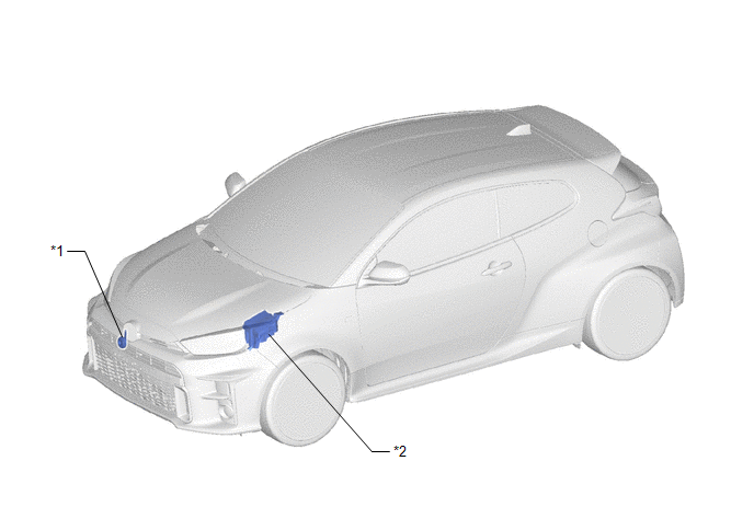
| *1 | LOW PITCHED HORN ASSEMBLY | *2 | NO. 1 ENGINE ROOM RELAY BLOCK AND NO. 1 JUNCTION BLOCK ASSEMBLY - HORN RELAY - HORN FUSE |
ILLUSTRATION
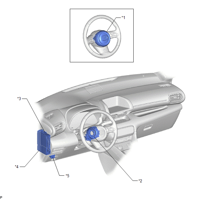
| *1 | HORN BUTTON ASSEMBLY | *2 | SPIRAL CABLE SUB-ASSEMBLY |
| *3 | MAIN BODY ECU (MULTIPLEX NETWORK BODY ECU) | *4 | POWER DISTRIBUTION BOX ASSEMBLY |
| *5 | DLC3 | - | - |
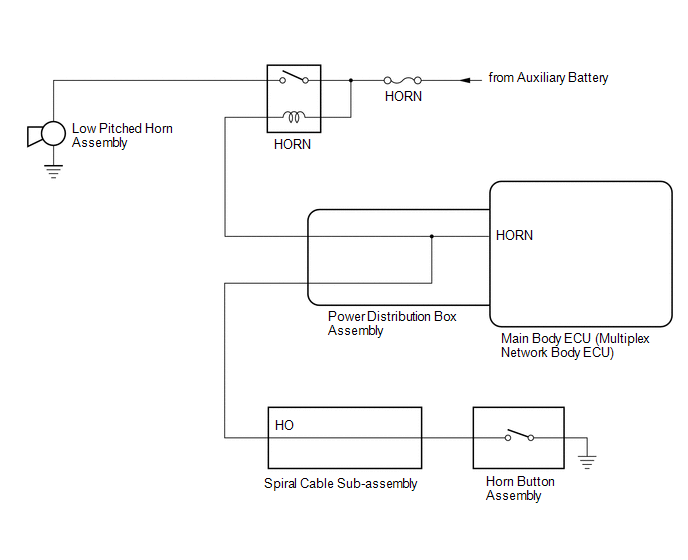
System Diagram
SYSTEM DIAGRAM
Problem Symptoms Table
PROBLEM SYMPTOMS TABLE
NOTICE:
If the main body ECU (multiplex network body ECU) is replaced, refer to the Registration.
Click here
.gif)
HINT:
Use the table below to help determine the cause of problem symptoms. If multiple suspected areas are listed, the potential causes of the symptoms are listed in order of probability in the "Suspected Area" column of the table. Check each symptom by checking the suspected areas in the order they are listed. Replace parts as necessary.
Horn System| Symptom | Suspected Area | Link |
|---|---|---|
| Horn does not sound | HORN fuse | - |
| HORN relay |
| |
| Horn button assembly | - | |
| Spiral cable sub-assembly |
| |
| Power distribution box assembly |
| |
| Harness or connector | - | |
| Horn sounds all the time | HORN relay |
|
| Horn button assembly | - | |
| Spiral cable sub-assembly |
| |
| Power distribution box assembly |
| |
| Main body ECU (Multiplex network body ECU) |
| |
| Harness or connector | - |
Data List / Active Test
DATA LIST / ACTIVE TEST
ACTIVE TEST
HINT:
Using the GTS to perform Active Tests allows relays, VSVs, actuators and other items to be operated without removing any parts. This non-intrusive functional inspection can be very useful because intermittent operation may be discovered before parts or wiring is disturbed. Performing Active Tests early in troubleshooting is one way to save diagnostic time. Data List information can be displayed while performing Active Tests.
(a) Perform the Active Test according to the display on the GTS.
Body Electrical > Main Body > Active Test| Tester Display | Measurement Item | Control Range | Diagnostic Note |
|---|---|---|---|
| Vehicle Horn | Vehicle horn | OFF or ON | - |
 Horn
Horn
ComponentsCOMPONENTS ILLUSTRATION
*1 LOW PITCHED HORN ASSEMBLY *2 RADIATOR UPPER AIR GUIDE PLATE
N*m (kgf*cm, ft.*lbf): Specified torque - - RemovalREMOVAL PROCEDURE 1...
 Relay
Relay
On-vehicle InspectionON-VEHICLE INSPECTION PROCEDURE 1. INSPECT HORN RELAY ASSEMBLY (a) Check the resistance. (1) Measure the resistance according to the value(s) in the table below...
Other information:
Toyota Yaris XP210 (2020-2026) Reapir and Service Manual: Installation
INSTALLATION PROCEDURE 1. INSTALL REAR SPOILER ASSEMBLY (a) Engage the clips to install the rear spoiler assembly. (b) Install the 2 bolts and 3 nuts. Torque: 5.5 N·m {56 kgf·cm, 49 in·lbf} (c) Remove the protective tape. 2. INSTALL REAR SPOILER HOLE COVER (a) Install the 4 rear spoiler hole covers...
Toyota Yaris XP210 (2020-2026) Reapir and Service Manual: Engine
ENGINE HINT: Perform these procedures after the engine has cooled down. INSPECT DRIVE BELT (a) Inspect the drive belt. Click here INSPECT ENGINE OIL (a) Inspect the engine oil. Click here REPLACE ENGINE OIL AND OIL FILTER (a) Replace the engine oil and oil filter...
Categories
- Manuals Home
- Toyota Yaris Owners Manual
- Toyota Yaris Service Manual
- Auto Lock/Unlock Function
- Fuel Gauge
- Opening and Closing the Liftgate/Trunk Lid
- New on site
- Most important about car
Refueling
Before refueling, close all the doors, windows, and the liftgate/trunk lid, and switch the ignition OFF.
To open the fuel-filler lid, pull the remote fuel-filler lid release.
