Toyota Yaris: Horn / Relay
On-vehicle Inspection
ON-VEHICLE INSPECTION
PROCEDURE
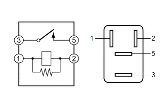
1. INSPECT HORN RELAY ASSEMBLY
(a) Check the resistance.
| (1) Measure the resistance according to the value(s) in the table below. Standard Resistance:
If the result is not as specified, replace the horn relay assembly. |
|
 Horn System
Parts LocationPARTS LOCATION ILLUSTRATION
*1 LOW PITCHED HORN ASSEMBLY *2 NO. 1 ENGINE ROOM RELAY BLOCK AND NO. 1 JUNCTION BLOCK ASSEMBLY - HORN RELAY - HORN FUSE ILLUSTRATION
*1 HORN BUTTON ASSEMBLY *2 SPIRAL CABLE SUB-ASSEMBLY *3 MAIN BODY ECU (MULTIPLEX NETWORK BODY ECU) *4 POWER DISTRIBUTION BOX ASSEMBLY *5 DLC3 - - System DiagramSYSTEM DIAGRAM
Problem Symptoms TablePROBLEM SYMPTOMS TABLE NOTICE: If the main body ECU (multiplex network body ECU) is replaced, refer to the Registration...

Other information:
Toyota Yaris XP210 (2020-2026) Reapir and Service Manual: Turbocharger Noise
DESCRIPTION HINT: Turbocharger noise is classified into two types. These are whistling sound and chattering sound. During troubleshooting, first determine the type of noise. Type of Abnormal Noise Outline of Abnormal Noise Major Trouble Area Whistling sound (airflow sound) The whistling sound volume and pitch are proportional to the turbocharger or engine speed...
Toyota Yaris XP210 (2020-2026) Owner's Manual: Installation on rear outboard seats
First, adjust the front seat to allow clearance between the child-restraint system and the front seat. Make sure the seatback is securely latched by pushing it back until it is fully locked. Expand the open seams on the rear of the seat bottom slightly to verify the locations of the LATCH lower anchors...
Categories
- Manuals Home
- Toyota Yaris Owners Manual
- Toyota Yaris Service Manual
- Headlights
- Removal
- Maintenance
- New on site
- Most important about car
Key Suspend Function
If a key is left in the vehicle, the functions of the key left in the vehicle are temporarily suspended to prevent theft of the vehicle.
To restore the functions, press the unlock button on the functions-suspended key in the vehicle.
Copyright © 2026 www.toyaris4.com