Toyota Yaris: Roof Headlining / Installation
INSTALLATION
PROCEDURE
1. INSTALL ROOF HEADLINING
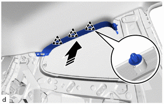
(a) Tilt the roof headlining diagonally and insert it into the cabin through the passenger side door as shown in the illustration.
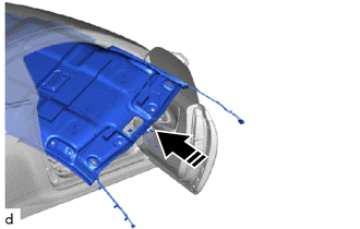
 | Insert in this Direction |
NOTICE:
- Check that the corners of the roof headlining are not folded, twisted or otherwise deformed and that none of the mounted parts have fallen off.
- Make sure that the roof headlining does not get caught on anything as it may become bent or damaged.
- Do not damage the roof headlining or vehicle interior.
(b) Connect the connector.
(c) Install the 3 clips.
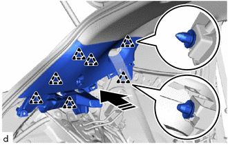
(d) for Front Pillar LH Side:
| (1) Engage the clamps. |
|
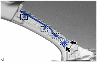
(2) Connect the 2 connectors.
(e) for Front Pillar RH Side:
| (1) Engage the clamps. |
|
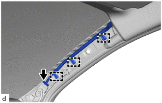
(2) Connect the connector.
(f) for Windshield Glass Side:
(1) w/o Pre-collision System:
- Connect the 2 connectors.
(2) w/ Pre-collision System:
- Connect the 4 connectors.
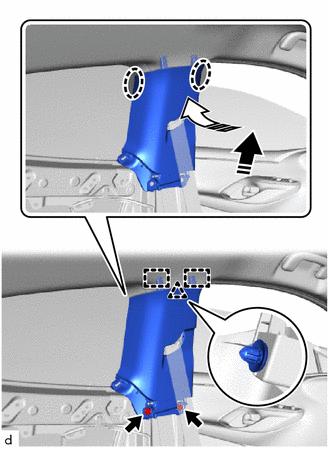
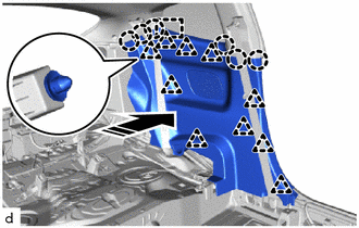
(g) for Rear Pillar RH Side:
| (1) Engage the clamps. |
|
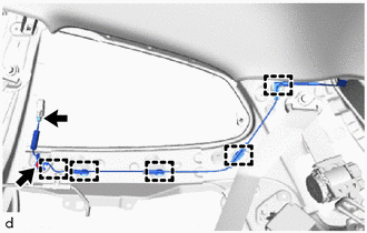
(2) Install the bolt.
Torque:
10 N·m {102 kgf·cm, 7 ft·lbf}
(3) Connect the connector.
2. INSTALL NO. 1 FORWARD RECOGNITION COVER (w/ Pre-collision System)
Click here

3. INSTALL NO. 2 FORWARD RECOGNITION COVER (w/ Pre-collision System)
Click here

4. INSTALL INNER REAR VIEW MIRROR STAY HOLDER COVER (w/o Pre-collision System)
Click here

5. INSTALL RAIN SENSOR COVER
Click here

6. INSTALL NO. 1 ROOM LIGHT ASSEMBLY
Click here

7. INSTALL MAP LIGHT ASSEMBLY
Click here

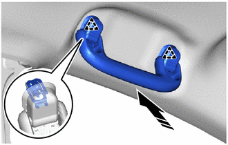
8. INSTALL ASSIST GRIP COVER
HINT:
Use the same procedure for all assist grip sub-assemblies.
| (a) Install the 2 assist grip covers and 2 clips to the assist grip sub-assembly. |
|
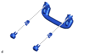
9. INSTALL ASSIST GRIP SUB-ASSEMBLY
HINT:
Use the same procedures for the opposite side.
(a) Engage the clips to install the assist grip sub-assembly as shown in the illustration.
 | Install in this Direction |
10. INSTALL VISOR HOLDER
HINT:
Use the same procedures for the opposite side.
(a) Engage the claws to install the base as shown in the illustration.
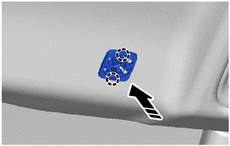
 | Install in this Direction |
(b) Install the visor holder as shown in the illustration.

 | Install in this Direction |
11. INSTALL VISOR ASSEMBLY LH
| (a) Engage the guide. |
|
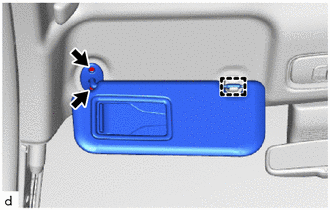
(b) Install the visor assembly with the 2 screws.
12. INSTALL VISOR ASSEMBLY RH
HINT:
Use the same procedure as for the LH side.
13. INSTALL ROOF SIDE INNER GARNISH LH
(a) Engage the clips to install the roof side inner garnish LH as shown in the illustration.
 | Install in this Direction |
14. INSTALL ROOF SIDE INNER GARNISH RH
HINT:
Use the same procedure as for the LH side.
15. INSTALL INNER ROOF SIDE GARNISH LH
(a) Engage the clips to install the inner roof side garnish LH as shown in the illustration.
 | Install in this Direction |
16. INSTALL INNER ROOF SIDE GARNISH RH
HINT:
Use the same procedure as for the LH side.
17. CONNECT REAR SEAT OUTER BELT ASSEMBLY LH
Click here

18. CONNECT REAR SEAT OUTER BELT ASSEMBLY RH
HINT:
Use the same procedure as for the LH side.
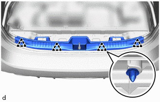
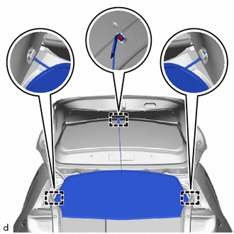
19. INSTALL DECK TRIM SIDE PANEL ASSEMBLY LH
(a) Install the 3 clips and deck trim side panel assembly LH.
20. INSTALL DECK TRIM SIDE PANEL ASSEMBLY RH
HINT:
Use the same procedure as for the LH side.
21. INSTALL DECK TRIM REAR COVER
| (a) Engage the clips to install the deck trim rear cover. |
|
22. INSTALL NO. 1 ROOF HEADLINING MOULDING LH
(a) Install the No. 1 roof headlining moulding LH.
23. INSTALL NO. 1 ROOF HEADLINING MOULDING RH
HINT:
Use the same procedure as for the LH side.
24. INSTALL CENTER PILLAR UPPER GARNISH LH
(a) Engage the guides and clip to install the center pillar upper garnish LH as shown in the illustration.
 | Install in this Direction (1) |
 | Install in this Direction (2) |
(b) Install the 2 clips.
25. INSTALL CENTER PILLAR UPPER GARNISH RH
HINT:
Use the same procedure as for the LH side.
26. INSTALL QUARTER TRIM PANEL ASSEMBLY LH
(a) Engage the guide, clips and claws to install the quarter trim panel assembly LH as shown in the illustration.
 | Install in this Direction |
27. INSTALL QUARTER TRIM PANEL ASSEMBLY RH
HINT:
Use the same procedure as for the LH side.
28. INSTALL REAR SEATBACK HINGE SUB-ASSEMBLY LH
(a) Install the rear seatback hinge sub-assembly with the bolt.
Torque:
18.1 N·m {185 kgf·cm, 13 ft·lbf}
29. INSTALL REAR SEATBACK HINGE SUB-ASSEMBLY RH
HINT:
Use the same procedure as for the LH side.
30. CONNECT FRONT SEAT OUTER BELT ASSEMBLY LH
Click here

31. CONNECT FRONT SEAT OUTER BELT ASSEMBLY RH
HINT:
Use the same procedure as for the LH side.
32. INSTALL LAP BELT OUTER ANCHOR COVER
HINT:
Use the same procedures for the opposite side.
Click here

33. INSTALL REAR SEAT ASSEMBLY
Click here

34. INSTALL FRONT DOOR OPENING TRIM WEATHERSTRIP LH
Click here

35. INSTALL FRONT DOOR OPENING TRIM WEATHERSTRIP RH
HINT:
Use the same procedure as for the LH side.
36. INSTALL DECK FLOOR BOX LH
(a) Install the deck floor box LH.
37. INSTALL DECK FLOOR BOX RH
(a) Install the deck floor box RH.
38. INSTALL DECK BOARD ASSEMBLY
(a) Install the deck board assembly.
39. INSTALL PACKAGE TRAY TRIM PANEL ASSEMBLY
| (a) Engage the hooks to install the package tray trim panel assembly. |
|
40. INSTALL FRONT SEAT ASSEMBLY LH
Click here

41. INSTALL FRONT SEAT ASSEMBLY RH
HINT:
Use the same procedure as for the LH side.
42. INSTALL NO. 2 HEATER TO REGISTER DUCT SUB-ASSEMBLY
Click here

43. INSTALL INSTRUMENT PANEL SUB-ASSEMBLY
Click here

 Reassembly
REASSEMBLY PROCEDURE 1. INSTALL NO. 2 ANTENNA CORD SUB-ASSEMBLY Click here
2. INSTALL NO. 1 ROOF WIRE (a) Apply butyl tape onto the roof headlining so that it does not protrude from the markings...

Other information:
Toyota Yaris XP210 (2020-2026) Reapir and Service Manual: Disassembly
DISASSEMBLY PROCEDURE 1. REMOVE BACK-UP LIGHT ASSEMBLY Click here 2. REMOVE NO. 2 LUGGAGE ROOM WIRE (a) Disengage the clamps to remove the No. 2 luggage room wire. 3. REMOVE REFLEX REFLECTOR ASSEMBLY LH (a) Remove the screw. (b) Disengage the claw and guide to remove the reflex reflector assembly LH...
Toyota Yaris XP210 (2020-2026) Reapir and Service Manual: Backup Boost Converter Circuit Board(Thermistor) Signal Compare Failure (P30DF62,P30EF4B,P323A00,P323A16,P323AA2,P323B29,P323B38)
DESCRIPTION Refer to DTC P323A19. Click here DTC No. Detection Item DTC Detection Condition Trouble Area Warning Indicate Memory Note P30DF62 Backup Boost Converter Circuit Board(Thermistor) Signal Compare Failure The following conditions is met for 1 second or more (1 trip detection logic): Difference in temperature between thermistor 1 and thermistor 2 of the engine stop and start ECU is 40°C (72°F) or higher...
Categories
- Manuals Home
- Toyota Yaris Owners Manual
- Toyota Yaris Service Manual
- Key Battery Replacement
- Battery Monitor Module General Electrical Failure (P058A01)
- Power Integration No.1 System Missing Message (B235287,B235587,B235787-B235987)
- New on site
- Most important about car
Keys

To use the auxiliary key, press the knob and pull out the auxiliary key from the smart key.
