Toyota Yaris: Rear Differential Carrier Assembly / Disassembly
DISASSEMBLY
CAUTION / NOTICE / HINT
NOTICE:
- Before installation, thoroughly clean and dry each part and then apply Toyota Genuine Differential gear oil LX SAE 75W-85 GL-5 or equivalent to them.
- Do not use alkaline cleaner for aluminum or rubber parts and rear differential case bolts.
- Do not clean rubber parts such as oil seals with non-residue solvent.
- Use an overhaul stand as necessary.
PROCEDURE
1. SEPARATE ELECTRO MAGNETIC CONTROL COUPLING WIRE HARNESS
| (a) Disengage the claw. |
|
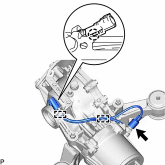
(b) Disconnect the temperature sensor connector.
(c) Disengage the 2 clamps to disconnect the electro magnetic control coupling wire harness from the rear differential carrier assembly.
NOTICE:
Do not damage the electro magnetic control coupling wire harness.
2. REMOVE CONNECTOR BRACKET
| (a) Remove the 3 bolts and 2 connector brackets from the rear differential carrier assembly. |
|
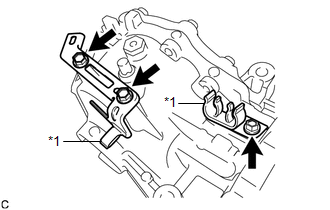
(b) Remove the 2 clamps from the 2 connector brackets.
3. REMOVE STUD BOLT
| (a) Install 2 service nuts to the stud bolt. Recommended Service Nut: Thread Diameter 10 mm (0.394 in.) Thread Pitch 1.0 mm (0.0394 in.) |
|
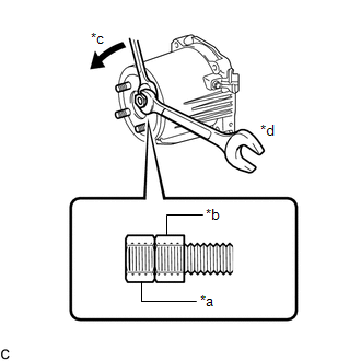
(b) Turn the lower nut and remove the other 3 stud bolts in the same way.
NOTICE:
Prevent foreign matter from entering the electro magnetic control coupling sub-assembly.
HINT:
- Lock the lower nut using the upper nut.
- If the threads of the electro magnetic control coupling sub-assembly are damaged while removing the stud bolt, replace the electro magnetic control coupling sub-assembly with a new one.
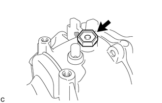
4. REMOVE REAR DIFFERENTIAL FILLER PLUG
| (a) Remove the rear differential filler plug and gasket. |
|
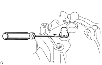
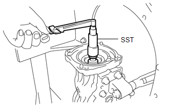
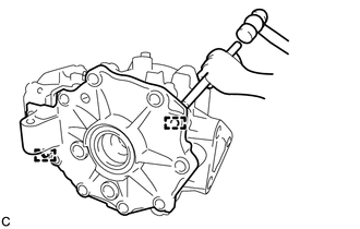
5. REMOVE REAR DIFFERENTIAL CARRIER COVER BREATHER PLUG
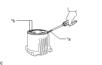
(a) Using a chisel and hammer, lift the rear differential carrier cover breather plug slightly.
| (b) Using a screwdriver, remove the rear differential carrier cover breather plug. |
|
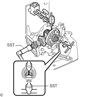
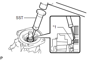
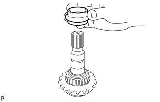
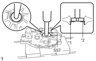
6. INSPECT RUNOUT OF ELECTRO MAGNETIC CONTROL COUPLING SUB-ASSEMBLY
(a) w/ LSD:
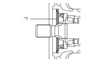
(1) Install a dial indicator and magnetic base perpendicular to the inner side of the electro magnetic control coupling sub-assembly as shown in the illustration.
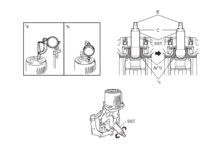
| *1 | Rear Differential Case Assembly | - | - |
| *a | Vertical Runout | *b | Lateral Runout |
| *c | Urethane | - | - |
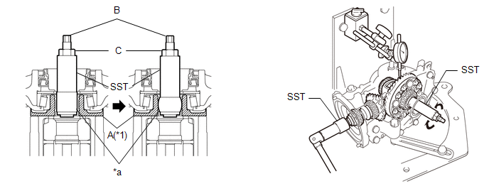
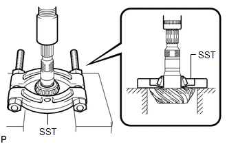
(2) Insert the urethane portion of SST until it reaches portion A shown in the illustration.
SST: 09564-52020
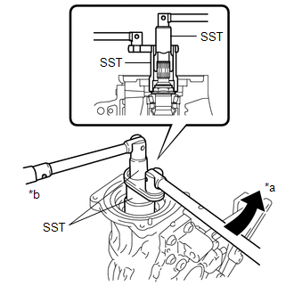
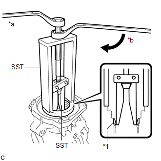
(3) Hold the B portion of SST and rotate the C portion, and continue expanding until the urethane portion of SST contacts the rear differential case assembly.
HINT:
If the urethane portion does not contact the rear differential case assembly, the rotation of SST and the rear differential case assembly will not be synchronized, and accurate measurement will be impossible.
(4) Using SST, rotate the electro magnetic control coupling sub-assembly forward and backward, and measure the vertical runout.
SST: 09564-52020
Maximum Runout:
0.06 mm (0.00236 in.)
If the runout is greater than the maximum value, replace the electro magnetic control coupling sub-assembly.
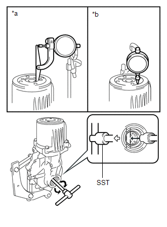
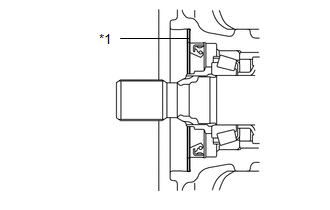
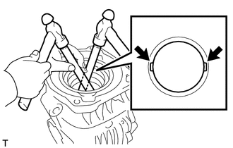
(5) Install a dial indicator and magnetic base perpendicular to the electro magnetic control coupling sub-assembly as shown in the illustration.
(6) Using SST, rotate the electro magnetic control coupling sub-assembly forward and backward, and measure the lateral runout.
SST: 09564-52020
Maximum Runout:
0.07 mm (0.00276 in.)
If the runout is greater than the maximum value, replace the electro magnetic control coupling sub-assembly.
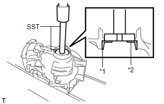
(b) w/o LSD:
| (1) Install a dial indicator and magnetic base perpendicular to the inner side of the electro magnetic control coupling sub-assembly as shown in the illustration. |
|
(2) Using SST, rotate the electro magnetic control coupling sub-assembly forward and backward, and measure the vertical runout.
SST: 09564-32011
Maximum Runout:
0.06 mm (0.00236 in.)
If the runout is greater than the maximum value, replace the electro magnetic control coupling sub-assembly.
(3) Install a dial indicator and magnetic base perpendicular to the electro magnetic control coupling sub-assembly as shown in the illustration.
(4) Using SST, rotate the electro magnetic control coupling sub-assembly forward and backward, and measure the lateral runout.
SST: 09564-32011
Maximum Runout:
0.07 mm (0.00276 in.)
If the runout is greater than the maximum value, replace the electro magnetic control coupling sub-assembly.
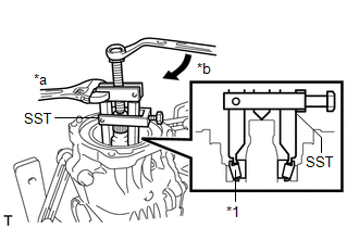
7. REMOVE ELECTRO MAGNETIC CONTROL COUPLING SUB-ASSEMBLY
| (a) Remove the 4 bolts. |
|
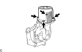
(b) Using a brass bar and a hammer, lightly tap the electro magnetic control coupling sub-assembly to remove it from the rear differential carrier assembly.
NOTICE:
- Set the brass bar on the ribbed part of the electro magnetic control coupling sub-assembly.
- Do not damage the contact surface.
HINT:
Temporarily install 2 bolts by approximately 5 or 6 threads to prevent the electro magnetic control coupling sub-assembly from falling.
8. REMOVE REAR DIFFERENTIAL DUST DEFLECTOR
| (a) Put matchmarks on the rear differential dust deflector and electro magnetic control coupling sub-assembly. |
|
(b) Using a screwdriver, remove the rear differential dust deflector.
NOTICE:
- Pry around the circumference of the rear differential dust deflector uniformly to prevent deformation.
- Do not damage the end surface of the electro magnetic control coupling sub-assembly.
HINT:
- Tape the screwdriver tip before use.
- If the end surface of the electro magnetic control coupling sub-assembly is damaged while removing the rear differential dust deflector, replace the electro magnetic control coupling sub-assembly with a new one.
9. REMOVE TRANSMISSION COUPLING CONICAL SPRING WASHER
| (a) Remove the transmission coupling conical spring washer from the rear differential carrier assembly. |
|
10. REMOVE TRANSMISSION COUPLING SPACER
| (a) Remove the transmission coupling spacer from the rear differential carrier assembly. |
|
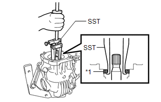
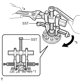
11. INSPECT DIFFERENTIAL RING GEAR BACKLASH
(a) w/ LSD:
(1) Insert a dial indicator and magnetic base through the rear differential filler plug hole, and set it perpendicular to a differential ring gear tooth tip.
| *1 | Rear Differential Case Assembly | - | - |
| *a | Urethane | - | - |
(2) Using SST, hold the differential drive pinion in place.
SST: 09556-16011
(3) Insert the urethane portion of SST until it reaches portion A shown in the illustration.
SST: 09564-52020
(4) Hold the B portion of SST and rotate the C portion, and continue expanding until the urethane portion of SST contacts the rear differential case assembly.
HINT:
If the urethane portion does not contact the rear differential case assembly, the rotation of SST and the rear differential case assembly will not be synchronized, and accurate measurement will be impossible.
(5) Using SST, rotate the rear differential case assembly forward and backward, and measure the backlash.
SST: 09564-52020
Backlash:
0.13 to 0.25 mm (0.00512 to 0.00984 in.)
If the backlash is not within the specification, adjust the side bearing preload or repair as necessary.
HINT:
Measure at 3 or more areas on the circumference of the differential ring gear.
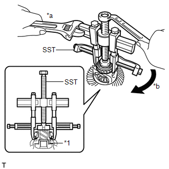
(b) w/o LSD:
| (1) Insert a dial indicator and magnetic base through the rear differential filler plug hole, and set it perpendicular to a differential ring gear tooth tip. |
|
(2) Using SST, hold the differential drive pinion in place.
SST: 09556-16011
(3) Using SST, rotate the rear differential case assembly forward and backward, and measure the backlash.
SST: 09564-32011
Backlash:
0.13 to 0.25 mm (0.00512 to 0.00984 in.)
If the backlash is not within the specification, adjust the side bearing preload or repair as necessary.
HINT:
Measure at 3 or more areas on the circumference of the differential ring gear.
12. INSPECT DIFFERENTIAL DRIVE PINION PRELOAD
| (a) Using SST and a torque wrench, inspect the differential drive pinion preload (starting torque) of the backlash between the differential drive pinion and differential ring gear. SST: 09556-16011 Standard Drive Pinion Preload: 1.51 to 2.52 N*m (16 to 25 kgf*cm, 14 to 22 in.*lbf) If the differential drive pinion preload is not within the specified range, adjust the differential drive pinion preload or repair as necessary. HINT: For a more accurate measurement, rotate the rear differential case bearing forward and backward before measuring. |
|
13. INSPECT TOTAL PRELOAD
| (a) Using SST and a torque wrench, inspect the total preload (starting torque) with the teeth of the differential drive pinion and differential ring gear in contact. SST: 09556-16011 Standard Total Preload: 2.80 to 5.34 N*m (29 to 54 kgf*cm, 25 to 47 in.*lbf) If the total preload is not within the specified range, adjust the total preload or repair as necessary. HINT: For a more accurate measurement, rotate the rear differential case bearing forward and backward before measuring. |
|

14. REMOVE REAR DRIVE SHAFT OIL SEAL LH
| (a) Using SST, remove the rear drive shaft oil seal LH from the rear differential carrier assembly. SST: 09308-00010 |
|
15. REMOVE REAR DRIVE SHAFT OIL SEAL RH
HINT:
Use the same procedure for the RH side and LH side.
16. REMOVE DIAPHRAGM OIL SEAL
| (a) Using SST, remove the diaphragm oil seal from the rear differential carrier assembly. SST: 09308-00010 |
|
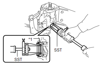
17. REMOVE REAR DRIVE PINION NUT
| (a) Using SST and a hammer, release the staked part of the rear drive pinion nut. SST: 09930-00010 NOTICE:
|
|
| (b) Using SST, hold the differential drive pinion in place and remove the rear drive pinion nut from the differential drive pinion. SST: 09556-16011 SST: 09564-16020 |
|
18. REMOVE REAR DRIVE PINION FRONT BEARING
| (a) Using SST, remove the rear drive pinion front tapered roller bearing (inner race) from the differential drive pinion. SST: 09556-40010 |
|
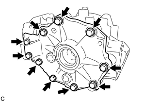
19. REMOVE DIFFERENTIAL SIDE BEARING RETAINER
| (a) Remove the 10 bolts from the rear differential carrier. |
|
| (b) Using a brass bar and a hammer, disengage the 2 pins and remove the differential side bearing retainer from the rear differential carrier. NOTICE:
HINT: Temporarily install 2 bolts by approximately 5 or 6 threads to prevent the differential side bearing retainer from falling. |
|
20. REMOVE REAR DIFFERENTIAL CASE ASSEMBLY
| (a) Remove the rear differential case assembly from the rear differential carrier. |
|
21. REMOVE DIFFERENTIAL DRIVE PINION
| (a) Remove the differential drive pinion from the rear differential carrier. |
|
22. REMOVE REAR DIFFERENTIAL DRIVE PINION OIL SLINGER
| (a) Remove the rear differential drive pinion oil slinger from the differential drive pinion. |
|
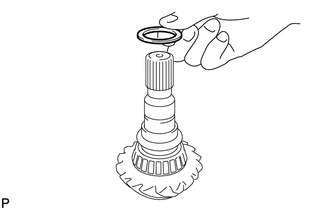
23. REMOVE REAR DIFFERENTIAL DRIVE PINION BEARING SPACER
| (a) Remove the rear differential drive pinion bearing spacer from the differential drive pinion. |
|
24. REMOVE REAR DRIVE PINION REAR BEARING
| (a) Using SST and a press, press out the rear drive pinion rear tapered roller bearing (inner race) from the differential drive pinion. SST: 09950-00020 NOTICE: Do not drop the differential drive pinion. HINT: If the differential driver pinion or differential ring gear is damaged, replace them both. |
|
(b) Remove the rear differential drive pinion plate washer.
25. REMOVE REAR DRIVE PINION FRONT BEARING
| (a) Using SST, remove the rear drive pinion front tapered roller bearing (outer race) from the rear differential carrier. SST: 09387-00041 09387-01030 09387-01041 SST: 09387-02020 |
|
26. REMOVE REAR DRIVE PINION REAR BEARING
| (a) Using a brass bar and a hammer, lightly and uniformly tap out the rear drive pinion rear tapered roller bearing (outer race) from the rear differential carrier. NOTICE: Set the brass bar on the notch. |
|
27. REMOVE REAR DIFFERENTIAL CASE BEARING (for LH Side)
| (a) Using SST and a press, remove the rear differential case bearing (LH side outer race) and rear differential side gear shaft plate washer from the differential side bearing retainer. SST: 09950-60011 09951-00540 SST: 09950-70010 09951-07100 |
|
28. REMOVE REAR DIFFERENTIAL CASE BEARING (for RH Side)
| (a) Using SST and a press, remove the rear differential case bearing (RH side outer race) and rear differential side gear shaft plate washer from the rear differential carrier. SST: 09950-60011 09951-00590 SST: 09950-70010 09951-07100 |
|
29. REMOVE REAR DIFFERENTIAL CASE BEARING (for LH Side)
HINT:
Perform this step only when replacing the rear differential case bearing or rear differential case sub-assembly.
| (a) Using SST, remove the rear differential case bearing (LH side inner race) from the rear differential case sub-assembly. SST: 09950-40011 09951-04020 09952-04010 09953-04020 09954-04010 09955-04011 09957-04010 09958-04011 SST: 09950-60011 09951-00340 NOTICE: Before using the SST center bolt (09953-04020), apply grease to its threads and tip. HINT:
|
|
30. REMOVE REAR DIFFERENTIAL CASE BEARING (for RH Side)
HINT:
Perform this step only when replacing the rear differential case bearing or rear differential case sub-assembly.
| (a) Using SST, remove the rear differential case bearing (RH side inner race) from the rear differential case sub-assembly. SST: 09950-40011 09951-04020 09952-04010 09953-04020 09954-04010 09955-04061 09957-04010 09958-04011 SST: 09950-60011 09951-00370 NOTICE: Before using the SST center bolt (09953-04020), apply grease to its threads and tip. HINT:
|
|
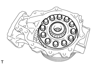
31. REMOVE DIFFERENTIAL RING GEAR
| (a) Secure the rear differential case sub-assembly in a vise between aluminum plates. NOTICE: Do not overtighten the vise. |
|
(b) Put matchmarks on the rear differential case sub-assembly and differential ring gear.
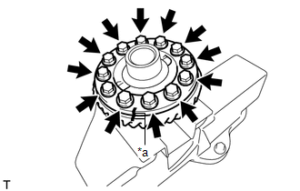
(c) Remove the 12 rear differential case bolts.
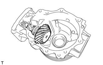
(d) Using a plastic hammer, lightly and uniformly tap the outer circumference of the differential ring gear to remove it from the rear differential case sub-assembly.
NOTICE:
- Be careful not to damage the edges of the differential ring gear.
- Do not drop the differential ring gear.
HINT:
- Place a cloth on the teeth side of the differential ring gear to prevent damage.
- If it is difficult to remove, tap the outer circumference of the differential ring gear using a brass bar and a hammer.
- If the differential drive pinion or differential ring gear is damaged, replace them both.
32. REMOVE REAR DIFFERENTIAL BREATHER PLUG OIL DEFLECTOR
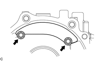
| (a) Remove the 2 bolts and rear differential breather plug oil deflector from the rear differential carrier. |
|
33. REMOVE STRAIGHT PIN
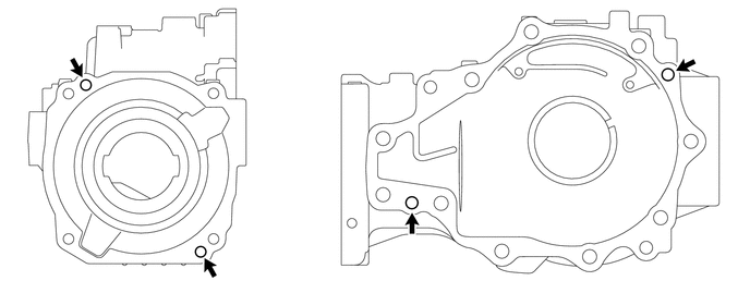
(a) Remove the 4 straight pins from the rear differential carrier.
34. INSPECT DIFFERENTIAL PINION AND SIDE GEAR
(a) Check the differential pinion gears and differential side gears for wear.
If the differential pinion gears and differential side gears are damaged, replace the rear differential case sub-assembly.
35. INSPECT DIFFERENTIAL CASE
(a) Check the differential case for cracks or damage.
If the differential case is damaged, replace the rear differential case sub-assembly.
 Removal
REMOVAL CAUTION / NOTICE / HINT The necessary procedures (adjustment, calibration, initialization, or registration) that must be performed after parts are removed and installed, or replaced during the rear differential carrier assembly removal/installation are shown below...
 Reassembly
REASSEMBLY CAUTION / NOTICE / HINT NOTICE:
Before installation, thoroughly clean and dry each part and then apply Toyota Genuine Differential gear oil LX SAE 75W-85 GL-5 or equivalent to them...
Other information:
Toyota Yaris XP210 (2020-2026) Owner's Manual: Dashboard Precautions
Prevent caustic solutions such as perfume and cosmetic oils from contacting the dashboard. They will damage and discolor the dashboard. If these solutions get on the dashboard, wipe them off immediately. Instrument panel top When cleaning, it is recommended that you use a clean towel dampened in a mild detergent to remove soiling...
Toyota Yaris XP210 (2020-2026) Reapir and Service Manual: Inspection
INSPECTION PROCEDURE 1. INSPECT TIE ROD END SUB-ASSEMBLY LH (a) Secure the tie rod end sub-assembly LH in a vise between aluminum plates. NOTICE: Do not overtighten the vise. (b) Install the nut to the stud bolt. (c) Flip the ball joint back and forth 5 times...
Categories
- Manuals Home
- Toyota Yaris Owners Manual
- Toyota Yaris Service Manual
- Brake System Control Module "A" System Voltage System Voltage Low (C137BA2)
- Power Integration No.1 System Missing Message (B235287,B235587,B235787-B235987)
- Engine Start Function When Key Battery is Dead
- New on site
- Most important about car
Key Suspend Function
If a key is left in the vehicle, the functions of the key left in the vehicle are temporarily suspended to prevent theft of the vehicle.
To restore the functions, press the unlock button on the functions-suspended key in the vehicle.