Toyota Yaris: Rear Differential Carrier Assembly / Reassembly
REASSEMBLY
CAUTION / NOTICE / HINT
NOTICE:
- Before installation, thoroughly clean and dry each part and then apply Toyota Genuine Differential gear oil LX SAE 75W-85 GL-5 or equivalent to them.
- Do not use alkaline cleaner for aluminum or rubber parts and rear differential case bolts.
- Do not clean rubber parts such as oil seals with non-residue solvent.
- Use an overhaul stand as necessary.
- Steps 8 to 15 are for temporary installation prior to adjustment.
PROCEDURE
1. INSTALL STRAIGHT PIN
(a) Using a plastic hammer, install the 4 straight pins to the rear differential carrier.
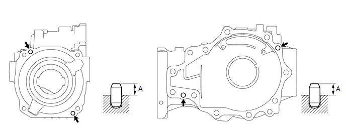
Protrusion (A):
8 to 9 mm (0.315 to 0.354 in.)
2. INSTALL REAR DIFFERENTIAL BREATHER PLUG OIL DEFLECTOR
| (a) Install the rear differential breather plug oil deflector with the 2 bolts. Torque: 6.5 N·m {66 kgf·cm, 58 in·lbf} |
|
3. INSTALL DIFFERENTIAL RING GEAR
(a) Clean the contact surfaces of the rear differential case sub-assembly and differential ring gear.
(b) Heat the differential ring gear in boiling water.
CAUTION:
Make sure to wear protective gloves as the ring gear is extremely hot.
(c) Carefully remove the differential ring gear from the boiling water.
(d) After the moisture on the differential ring gear has completely evaporated, quickly temporarily install the differential ring gear to the rear differential case sub-assembly.
(e) Secure the rear differential case sub-assembly between aluminum plates in a vise.
NOTICE:
Do not overtighten the vise.
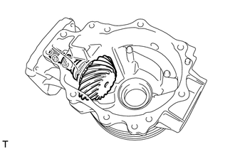
| (f) Align the matchmarks on the rear differential case sub-assembly and differential ring gear, and install the differential ring gear. HINT: Align the bolt holes of the rear differential case sub-assembly and differential ring gear. |
|
(g) Temporarily install 12 new rear differential case bolts to which thread lock has been applied.
Adhesive:
Toyota Genuine Adhesive 1360K, Three Bond 1360K or equivalent.
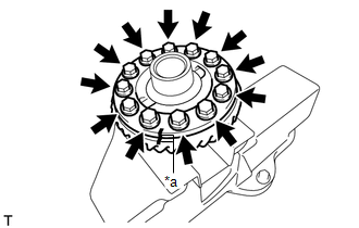
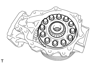
(h) After the ring gear has cooled sufficiently, tighten the 12 new rear differential case bolts.
Torque:
98.6 N·m {1005 kgf·cm, 73 ft·lbf}
NOTICE:
- New rear differential case bolts should be used every time the differential ring gear is installed.
- Install the new rear differential case bolts by tightening diametrically opposite bolts uniformly in several passes.
- Tighten the rear differential case bolts after the differential ring gear has cooled down sufficiently.
- Do not allow any oil to contact the rear differential case bolt, differential ring gear threads or differential case seating surface.
4. INSTALL REAR DIFFERENTIAL CASE BEARING (for LH Side)
NOTICE:
New bearings are coated with anti-rust oil. If using new bearings, do not wash it off.
HINT:
- Perform this step only when replacing the rear differential case bearing or rear differential case sub-assembly.
- As the rear differential case bearing (LH side inner race) is damaged during removal, make sure to use a new one.
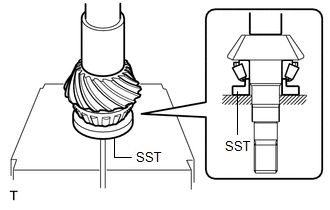
| (a) Using SST and a press, install a new rear differential case bearing (LH side inner race) to the rear differential case sub-assembly. SST: 09223-46011 NOTICE: Replace the inner and outer races as a set. |
|
5. INSTALL REAR DIFFERENTIAL CASE BEARING (for RH Side)
NOTICE:
New bearings are coated with anti-rust oil. If using new bearings, do not wash it off.
HINT:
Perform this step only when replacing the rear differential case bearing or rear differential case sub-assembly.
| (a) Using SST and a press, install the rear differential case bearing (RH side inner race) to the rear differential case sub-assembly. SST: 09223-46011 NOTICE: Replace the inner and outer races as a set. |
|
6. INSTALL REAR DRIVE PINION REAR BEARING
NOTICE:
New bearings are coated with anti-rust oil. If using new bearings, do not wash it off.
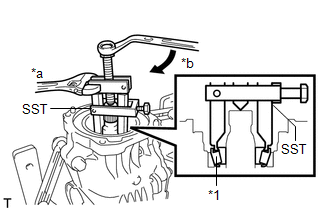
| (a) Using SST, bolt, nut and washers, install the rear drive pinion rear tapered roller bearing (outer race) to the rear differential carrier. SST: 09950-60011 09951-00500 09951-00530 SST: 09950-60021 09951-00680 09951-00890 NOTICE: Replace the inner and outer races as a set. Recommended Bolt, Nut: Thread Diameter 12 mm (0.472 in.) Thread Pitch 1.5 mm (0.0591 in.) Bolt with Shaft Lengths 124 mm (4.88 in.) |
|
7. INSTALL REAR DRIVE PINION FRONT BEARING
NOTICE:
New bearings are coated with anti-rust oil. If using new bearings, do not wash it off.
| (a) Using SST and a press, install the rear drive pinion front tapered roller bearing (outer race) to the rear differential carrier. SST: 09950-60011 09951-00610 SST: 09950-70010 09951-07150 NOTICE: Replace the inner and outer races as a set. |
|
8. INSTALL REAR DRIVE PINION REAR BEARING
NOTICE:
New bearings are coated with anti-rust oil. If using new bearings, do not wash it off.
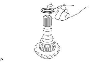
| (a) Install the rear differential drive pinion plate washer to the differential drive pinion. NOTICE: Install each rear differential drive pinion plate washer to the position it was removed from. |
|

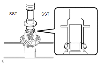
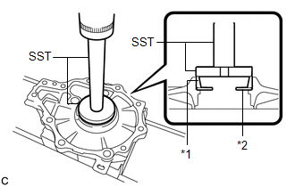
| (b) Using SST and a press, install the rear drive pinion rear tapered roller bearing (inner race) to the differential drive pinion. SST: 09506-30012 NOTICE: Replace the inner and outer races as a set. |
|
9. INSTALL REAR DIFFERENTIAL CASE BEARING (for LH Side)
NOTICE:
New bearings are coated with anti-rust oil. If using new bearings, do not wash it off.
HINT:
Replace the rear differential case bearing (LH side outer race) when removing the rear differential case bearing (LH side inner race) from the rear differential case sub-assembly.
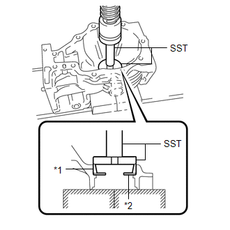
| (a) Using SST and a press, install the rear differential side gear shaft plate washer and rear differential case bearing (LH side outer race) to the differential side bearing retainer. SST: 09950-60021 09951-00680 SST: 09950-70010 09951-07150 NOTICE:
|
|
10. INSTALL REAR DIFFERENTIAL CASE BEARING (for RH Side)
NOTICE:
New bearings are coated with anti-rust oil. If using new bearings, do not wash it off.
| (a) Using SST and a press, install the rear differential side gear shaft plate washer and rear differential case bearing (RH side outer race) to the rear differential carrier. SST: 09950-60021 09951-00680 SST: 09950-70010 09951-07150 NOTICE:
|
|
11. ADJUST DIFFERENTIAL DRIVE PINION PRELOAD
| (a) Install the differential drive pinion with rear drive pinion rear tapered roller bearing (inner race) to the rear differential carrier. |
|

(b) Apply hypoid gear oil LSD to the threads of a new rear drive pinion nut and its seating surface.
(c) Install the rear drive pinion front tapered roller bearing (inner race) and rear drive pinion nut to the differential drive pinion.
NOTICE:
- New bearings are coated with anti-rust oil. If using new bearings, do not wash it off.
- Replace the inner and outer races as a set.
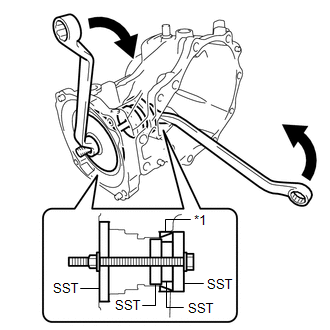
| (d) Using SST, gradually tighten the rear drive pinion nut until the specified preload is reached. Do not exceed the torque limit shown below. SST: 09556-16011 SST: 09564-16020 Torque: Specified tightening torque 321 N*m (3273 kgf*cm, 237 ft.*lbf) or less NOTICE:
HINT:
|
|


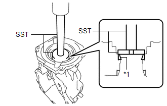
| (e) Using SST and a torque wrench, measure the preload (starting torque) of the differential drive pinion. SST: 09556-16011 Standard Drive Pinion Preload (Starting Torque): New Bearing 1.83 to 3.04 N*m (19 to 30 kgf*cm, 17 to 26 in.*lbf) Reused Bearing 1.51 to 2.52 N*m (16 to 25 kgf*cm, 14 to 22 in.*lbf) HINT:
|
|
12. INSTALL REAR DIFFERENTIAL CASE ASSEMBLY
(a) Using a scraper and wire brush, remove the seal packing from the rear differential carrier and differential side bearing retainer.
NOTICE:
- Do not damage the contact surface.
- Be sure to completely remove all seal packing from the rear differential carrier and differential side bearing retainer.
- Do not allow the removed seal packing to enter the rear differential carrier.
(b) Using a non-residue solvent, remove grease and oil from the contact surfaces of the rear differential carrier and differential side bearing retainer.
NOTICE:
Do not damage the contact surface.
| (c) Install the rear differential case assembly to the rear differential carrier. |
|

| (d) Install the differential side bearing retainer to the rear differential carrier with the 10 bolts. Torque: 42.2 N·m {430 kgf·cm, 31 ft·lbf} |
|

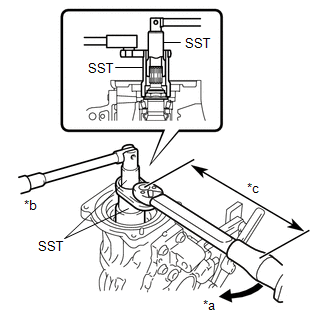
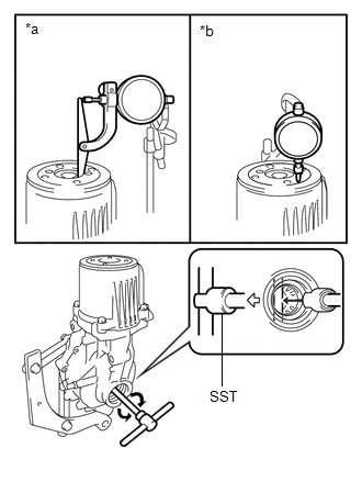
13. INSPECT DIFFERENTIAL RING GEAR BACKLASH
(a) w/ LSD:
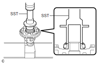
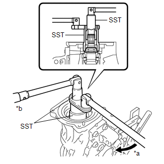
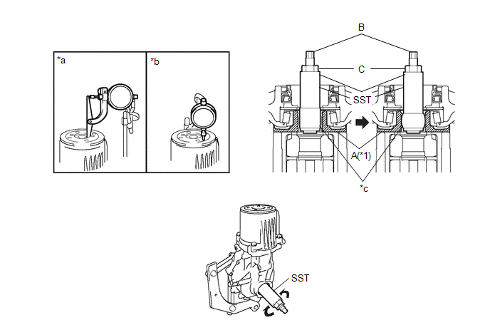
(1) Insert a dial indicator and magnetic base through the rear differential filler plug hole, and set it perpendicular to a differential ring gear tooth tip.
| *1 | Rear Differential Case Assembly | - | - |
| *a | Urethane | - | - |
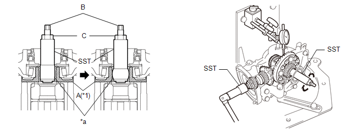
(2) Using SST, hold the differential drive pinion in place.
SST: 09556-16011
(3) Insert the urethane portion of SST until it reaches portion A shown in the illustration.
SST: 09564-52020
(4) Hold the B portion of SST and rotate the C portion, and continue expanding until the urethane portion of SST contacts the rear differential case assembly.
HINT:
If the urethane portion does not contact the rear differential case assembly, the rotation of SST and the rear differential case assembly will not be synchronized, and accurate measurement will be impossible.
(5) Using SST, rotate the rear differential case assembly forward and backward, and measure the backlash.
SST: 09564-52020
Backlash:
0.13 to 0.25 mm (0.00512 to 0.00984 in.)
HINT:
Measure at 3 or more areas on the circumference of the differential ring gear.
(6) If the result is not within the specified range, select rear differential side gear shaft plate washers that are thicker or thinner as necessary. Adjust the thickness of the left and right rear differential side gear shaft plate washers in equal increments. Then install the rear differential case bearing (outer race).
HINT:
- Adjust the thickness of the LH and RH rear differential side gear shaft plate washers by the same amount each time until the backlash is within the standard range. If the thickness on the LH side is increased, decrease the thickness on the RH side, and if the thickness on the LH side is decreased, increase the thickness on the RH side.
- When the backlash is smaller than the specified value, select a thick rear differential side gear shaft plate washer for the RH side and thin rear differential side gear shaft plate washer for the LH side.
- When the backlash is larger than the specified value, select a thin rear differential side gear shaft plate washer for the RH side and thick rear differential side gear shaft plate washer for the LH side.
Rear Differential Side Gear Shaft Plate Washer:
| Mark | Thickness | Mark | Thickness |
|---|---|---|---|
| 75 | 1.74 to 1.76 mm (0.0686 to 0.0692 in.) | 96 | 2.34 to 2.36 mm (0.0922 to 0.0929 in.) |
| 76 | 1.77 to 1.79 mm (0.0697 to 0.0704 in.) | 97 | 2.37 to 2.39 mm (0.0934 to 0.0940 in.) |
| 77 | 1.80 to 1.82 mm (0.0709 to 0.0716 in.) | 98 | 2.40 to 2.42 mm (0.0945 to 0.0952 in.) |
| 78 | 1.83 to 1.85 mm (0.0721 to 0.0728 in.) | 99 | 2.43 to 2.45 mm (0.0957 to 0.0964 in.) |
| 79 | 1.86 to 1.88 mm (0.0733 to 0.0740 in.) | 00 | 2.46 to 2.48 mm (0.0969 to 0.0976 in.) |
| 80 | 1.89 to 1.91 mm (0.0745 to 0.0751 in.) | 01 | 2.49 to 2.51 mm (0.0981 to 0.0988 in.) |
| 81 | 1.92 to 1.94 mm (0.0756 to 0.0763 in.) | 02 | 2.52 to 2.54 mm (0.0993 to 0.0999 in.) |
| 82 | 1.95 to 1.97 mm (0.0768 to 0.0775 in.) | 03 | 2.55 to 2.57 mm (0.1004 to 0.1011 in.) |
| 83 | 1.98 to 2.00 mm (0.0780 to 0.0787 in.) | 04 | 2.58 to 2.60 mm (0.1016 to 0.1023 in.) |
| 84 | 2.01 to 2.03 mm (0.0792 to 0.0799 in.) | 05 | 2.61 to 2.63 mm (0.1028 to 0.1035 in.) |
| 85 | 2.04 to 2.06 mm (0.0804 to 0.0811 in.) | 06 | 2.64 to 2.66 mm (0.1040 to 0.1047 in.) |
| 86 | 2.07 to 2.09 mm (0.0815 to 0.0822 in.) | 07 | 2.67 to 2.69 mm (0.1052 to 0.1059 in.) |
| 88 | 2.10 to 2.12 mm (0.0827 to 0.0834 in.) | 08 | 2.70 to 2.72 mm (0.1063 to 0.1070 in.) |
| 89 | 2.13 to 2.15 mm (0.0839 to 0.0846 in.) | 09 | 2.73 to 2.75 mm (0.1075 to 0.1082 in.) |
| 90 | 2.16 to 2.18 mm (0.0851 to 0.0858 in.) | 10 | 2.76 to 2.78 mm (0.1087 to 0.1094 in.) |
| 91 | 2.19 to 2.21 mm (0.0863 to 0.0870 in.) | 11 | 2.79 to 2.81 mm (0.1099 to 0.1106 in.) |
| 92 | 2.22 to 2.24 mm (0.0875 to 0.0881 in.) | 12 | 2.82 to 2.84 mm (0.1111 to 0.1118 in.) |
| 93 | 2.25 to 2.27 mm (0.0886 to 0.0893 in.) | 13 | 2.85 to 2.87 mm (0.1123 to 0.1129 in.) |
| 94 | 2.28 to 2.30 mm (0.0898 to 0.0905 in.) | 14 | 2.88 to 2.90 mm (0.1134 to 0.1141 in.) |
| 95 | 2.31 to 2.33 mm (0.0910 to 0.0917 in.) | - | - |
(b) w/o LSD:
| (1) Insert a dial indicator and magnetic base through the rear differential filler plug hole, and set it perpendicular to a differential ring gear tooth tip. |
|

(2) Using SST, hold the differential drive pinion in place.
SST: 09556-16011
(3) Using SST, rotate the rear differential case assembly forward and backward, and measure the backlash.
SST: 09564-32011
Backlash:
0.13 to 0.25 mm (0.00512 to 0.00984 in.)
HINT:
Measure at 3 or more areas on the circumference of the differential ring gear.
(4) If the result is not within the specified range, select rear differential side gear shaft plate washers that are thicker or thinner as necessary. Adjust the thickness of the left and right rear differential side gear shaft plate washers in equal increments. Then install the rear differential case bearing (outer race).
HINT:
- Adjust the thickness of the LH and RH rear differential side gear shaft plate washers by the same amount each time until the backlash is within the standard range. If the thickness on the LH side is increased, decrease the thickness on the RH side, and if the thickness on the LH side is decreased, increase the thickness on the RH side.
- When the backlash is smaller than the specified value, select a thick rear differential side gear shaft plate washer for the RH side and thin rear differential side gear shaft plate washer for the LH side.
- When the backlash is larger than the specified value, select a thin rear differential side gear shaft plate washer for the RH side and thick rear differential side gear shaft plate washer for the LH side.
Rear Differential Side Gear Shaft Plate Washer:
| Mark | Thickness | Mark | Thickness |
|---|---|---|---|
| 75 | 1.74 to 1.76 mm (0.0686 to 0.0692 in.) | 96 | 2.34 to 2.36 mm (0.0922 to 0.0929 in.) |
| 76 | 1.77 to 1.79 mm (0.0697 to 0.0704 in.) | 97 | 2.37 to 2.39 mm (0.0934 to 0.0940 in.) |
| 77 | 1.80 to 1.82 mm (0.0709 to 0.0716 in.) | 98 | 2.40 to 2.42 mm (0.0945 to 0.0952 in.) |
| 78 | 1.83 to 1.85 mm (0.0721 to 0.0728 in.) | 99 | 2.43 to 2.45 mm (0.0957 to 0.0964 in.) |
| 79 | 1.86 to 1.88 mm (0.0733 to 0.0740 in.) | 00 | 2.46 to 2.48 mm (0.0969 to 0.0976 in.) |
| 80 | 1.89 to 1.91 mm (0.0745 to 0.0751 in.) | 01 | 2.49 to 2.51 mm (0.0981 to 0.0988 in.) |
| 81 | 1.92 to 1.94 mm (0.0756 to 0.0763 in.) | 02 | 2.52 to 2.54 mm (0.0993 to 0.0999 in.) |
| 82 | 1.95 to 1.97 mm (0.0768 to 0.0775 in.) | 03 | 2.55 to 2.57 mm (0.1004 to 0.1011 in.) |
| 83 | 1.98 to 2.00 mm (0.0780 to 0.0787 in.) | 04 | 2.58 to 2.60 mm (0.1016 to 0.1023 in.) |
| 84 | 2.01 to 2.03 mm (0.0792 to 0.0799 in.) | 05 | 2.61 to 2.63 mm (0.1028 to 0.1035 in.) |
| 85 | 2.04 to 2.06 mm (0.0804 to 0.0811 in.) | 06 | 2.64 to 2.66 mm (0.1040 to 0.1047 in.) |
| 86 | 2.07 to 2.09 mm (0.0815 to 0.0822 in.) | 07 | 2.67 to 2.69 mm (0.1052 to 0.1059 in.) |
| 88 | 2.10 to 2.12 mm (0.0827 to 0.0834 in.) | 08 | 2.70 to 2.72 mm (0.1063 to 0.1070 in.) |
| 89 | 2.13 to 2.15 mm (0.0839 to 0.0846 in.) | 09 | 2.73 to 2.75 mm (0.1075 to 0.1082 in.) |
| 90 | 2.16 to 2.18 mm (0.0851 to 0.0858 in.) | 10 | 2.76 to 2.78 mm (0.1087 to 0.1094 in.) |
| 91 | 2.19 to 2.21 mm (0.0863 to 0.0870 in.) | 11 | 2.79 to 2.81 mm (0.1099 to 0.1106 in.) |
| 92 | 2.22 to 2.24 mm (0.0875 to 0.0881 in.) | 12 | 2.82 to 2.84 mm (0.1111 to 0.1118 in.) |
| 93 | 2.25 to 2.27 mm (0.0886 to 0.0893 in.) | 13 | 2.85 to 2.87 mm (0.1123 to 0.1129 in.) |
| 94 | 2.28 to 2.30 mm (0.0898 to 0.0905 in.) | 14 | 2.88 to 2.90 mm (0.1134 to 0.1141 in.) |
| 95 | 2.31 to 2.33 mm (0.0910 to 0.0917 in.) | - | - |
14. ADJUST TOOTH CONTACT BETWEEN RING GEAR AND DRIVE PINION
(a) Remove the 10 bolts and the differential side bearing retainer.
(b) Remove the rear differential case assembly from the rear differential carrier.
(c) Coat 3 or 4 teeth at 4 different positions on the differential ring gear with Prussian blue.
(d) Install the rear differential case assembly to the rear differential carrier.
(e) Install the differential side bearing retainer with the 10 bolts.
Torque:
42.2 N·m {430 kgf·cm, 31 ft·lbf}
(f) Turn the differential drive pinion at least 10 times.
(g) Remove the 10 bolts and the differential side bearing retainer.
(h) Remove the rear differential case assembly from the rear differential carrier.
(i) Inspect the tooth contact pattern.
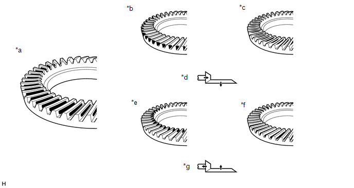
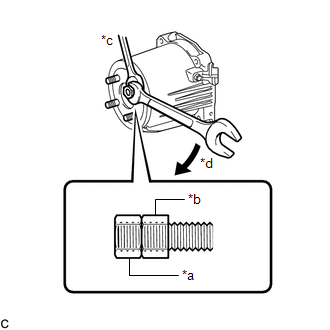
| *a | Proper Contact | *b | Heel Contact |
| *c | Face Contact | *d | Select washers that will bring the drive pinion closer to the ring gear |
| *e | Toe Contact | *f | Flank Contact |
| *g | Select washers that will bring the drive pinion away from the ring gear | - | - |
HINT:
Check the tooth contact pattern at 2 or more positions on the circumference of the differential ring gear.
(j) Perform the following procedure for face or flank contact:
(1) If the result is not within the specified range, select rear differential side gear shaft plate washers that are thicker or thinner as necessary. Adjust the thickness of the left and right rear differential side gear shaft plate washers in equal increments. Then install the rear differential case bearing (outer race).
(2) Repeat the differential ring gear and differential drive pinion tooth contact pattern inspection.
HINT:
If the tooth contact pattern is not correct, reselect rear differential side gear shaft plate washers and reinspect the tooth contact pattern.
(3) Repeat the differential ring gear and differential drive pinion backlash inspection.
HINT:
If the differential ring gear and differential drive pinion backlash are not as specified, reselect the rear differential drive pinion plate washer and then readjust the differential drive pinion preload, differential ring gear and differential drive pinion backlash and reinspect the tooth contact pattern.
(k) Perform the following procedure for heel or toe contact:
| (1) Select a rear differential drive pinion plate washer again and install the rear drive pinion rear tapered roller bearing (inner race). Rear Differential Drive Pinion Plate Washer:
|
|
(l) Readjust the differential drive pinion preload, differential ring gear and differential drive pinion backlash and reinspect the tooth contact pattern.
15. INSPECT TOTAL PRELOAD
| (a) Using SST and a torque wrench, measure the total preload (starting torque) with the teeth of the differential drive pinion and differential ring gear in contact. SST: 09556-16011 Standard Total Preload (Starting Torque): New Bearing 3.12 to 5.86 N*m (32 to 59 kgf*cm, 28 to 51 in.*lbf) Reused Bearing 2.80 to 5.34 N*m (29 to 54 kgf*cm, 25 to 47 in.*lbf) HINT: For a more accurate measurement, rotate the rear differential case bearing forward and backward before measuring. |
|

(b) If the results are not within the specification, perform the procedure below:
(1) Select a thicker or thinner rear differential side gear shaft plate washer for the RH side, and then install the rear differential case bearing outer race (RH side only).
(2) Repeat the total preload measurement.
(3) Repeat the differential ring gear and differential drive pinion backlash inspection.
(4) Repeat the differential ring gear and differential drive pinion tooth contact pattern inspection.
16. REMOVE DIFFERENTIAL SIDE BEARING RETAINER

(a) Remove the 10 bolts and differential side bearing retainer.
17. REMOVE REAR DIFFERENTIAL CASE ASSEMBLY
| (a) Remove the rear differential case assembly from the rear differential carrier. |
|
18. REMOVE DIFFERENTIAL DRIVE PINION
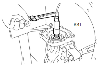
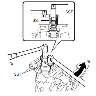
| (a) Using SST, hold the differential drive pinion in place and remove the rear drive pinion nut from the differential drive pinion. SST: 09556-16011 SST: 09564-16020 |
|
| (b) Using SST, remove the rear drive pinion front tapered roller bearing (inner race) from the differential drive pinion. SST: 09556-40010 NOTICE: Do not drop the differential drive pinion. |
|
19. INSTALL REAR DIFFERENTIAL DRIVE PINION BEARING SPACER
| (a) Install a new rear differential drive pinion bearing spacer to the differential drive pinion. HINT: Face the smaller inside diameter towards the front of the vehicle. |
|

20. INSTALL REAR DIFFERENTIAL DRIVE PINION OIL SLINGER
| (a) Install the rear differential drive pinion oil slinger to the differential drive pinion. |
|
21. INSTALL DIFFERENTIAL DRIVE PINION
| (a) Install the differential drive pinion to the rear differential carrier. |
|
22. TEMPORARILY TIGHTEN REAR DRIVE PINION NUT
(a) Apply hypoid gear oil LSD to the threads of the rear drive pinion nut and its seating surface.
(b) Temporarily install the rear drive pinion front tapered roller bearing (inner race) and rear drive pinion nut to the differential drive pinion.
| (c) Using SST, temporarily tighten the rear drive pinion nut to the differential drive pinion. SST: 09556-16011 SST: 09564-16020 |
|
23. ADJUST DIFFERENTIAL DRIVE PINION PRELOAD
| (a) Using SST and a torque wrench, inspect the differential drive pinion preload (starting torque). SST: 09556-16011 Standard Drive Pinion Preload (Starting Torque): New Bearing 1.83 to 3.04 N*m (19 to 30 kgf*cm, 17 to 26 in.*lbf) Reused Bearing 1.51 to 2.52 N*m (16 to 25 kgf*cm, 14 to 22 in.*lbf) HINT:
|
|

| (b) If the preload is insufficient, use SST to tighten the rear drive pinion nut 5° to 10° at a time. Measure the drive pinion preload and repeat the adjustment as necessary until the preload matches the specified torque. SST: 09556-16011 SST: 09564-16020 Torque: Specified tightening torque 321 N*m (3273 kgf*cm, 237 ft.*lbf) or less NOTICE:
HINT:
|
|

(c) If the tightening torque of the rear drive pinion nut exceeds the specified torque but the preload is still insufficient, remove the rear drive pinion nut. Then check if the rear drive pinion nut and differential drive pinion screw threads are damaged.
(d) If no damage is found, replace the rear differential drive pinion bearing spacer, apply hypoid gear oil LSD to rear drive pinion nut threads and its seating surface, and repeat the procedure above.
24. INSTALL REAR DIFFERENTIAL CASE ASSEMBLY
| (a) Install the rear differential case assembly to the rear differential carrier. |
|

25. INSTALL DIFFERENTIAL SIDE BEARING RETAINER
| (a) Install the differential side bearing retainer to the rear differential carrier with the 10 bolts. Torque: 42.2 N·m {430 kgf·cm, 31 ft·lbf} |
|

26. INSPECT DIFFERENTIAL RING GEAR BACKLASH
(a) w/ LSD:
(1) Insert a dial indicator and magnetic base through the rear differential filler plug hole, and set it perpendicular to a differential ring gear tooth tip.

| *1 | Rear Differential Case Assembly | - | - |
| *a | Urethane | - | - |
(2) Using SST, hold the differential drive pinion in place.
SST: 09556-16011
(3) Insert the urethane portion of SST until it reaches portion A shown in the illustration.
SST: 09564-52020
(4) Hold the B portion of SST and rotate the C portion, and continue expanding until the urethane portion of SST contacts the rear differential case assembly.
HINT:
If the urethane portion does not contact the rear differential case assembly, the rotation of SST and the rear differential case assembly will not be synchronized, and accurate measurement will be impossible.
(5) Using SST, rotate the rear differential case assembly forward and backward, and measure the backlash.
SST: 09564-52020
Backlash:
0.13 to 0.25 mm (0.00512 to 0.00984 in.)
HINT:
Measure at 3 or more areas on the circumference of the differential ring gear.
(b) w/o LSD:
| (1) Insert a dial indicator and magnetic base through the rear differential filler plug hole, and set it perpendicular to a differential ring gear tooth tip. |
|
(2) Using SST, hold the differential drive pinion in place.
SST: 09556-16011
(3) Using SST, rotate the rear differential case assembly forward and backward, and measure the backlash.
SST: 09564-32011
Backlash:
0.13 to 0.25 mm (0.00512 to 0.00984 in.)
HINT:
Measure at 3 or more areas on the circumference of the differential ring gear.
27. INSPECT TOTAL PRELOAD
| (a) Using SST and a torque wrench, measure the total preload (starting torque) with the teeth of the differential drive pinion and differential ring gear in contact. SST: 09556-16011 Standard Total Preload (Starting Torque): New Bearing 3.12 to 5.86 N*m (32 to 59 kgf*cm, 28 to 51 in.*lbf) Reused Bearing 2.80 to 5.34 N*m (29 to 54 kgf*cm, 25 to 47 in.*lbf) HINT: For a more accurate measurement, rotate the rear differential case bearing forward and backward before measuring. |
|

(b) If the results are not within the specification, perform the procedure below:
(1) Select a thicker or thinner rear differential side gear shaft plate washer for the RH side, and then install the rear differential case bearing outer race (RH side only).
(2) Repeat the total preload measurement.
(3) Repeat the differential ring gear and differential drive pinion backlash inspection.
(4) Repeat the differential ring gear and differential drive pinion tooth contact pattern inspection.
28. REMOVE DIFFERENTIAL SIDE BEARING RETAINER
| (a) Remove the 10 bolts and differential side bearing retainer. |
|

29. INSTALL DIFFERENTIAL SIDE BEARING RETAINER
(a) Using a non-residue solvent, remove grease and oil from the contact surfaces of the rear differential carrier and differential side bearing retainer.
NOTICE:
Do not damage the contact surface.
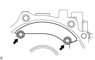
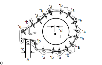
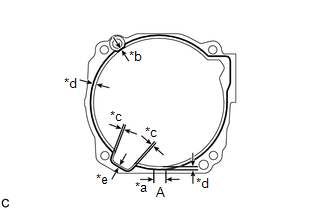
| (b) Apply seal packing to the areas indicated in the illustration of the rear differential carrier. Seal Packing: Toyota Genuine Seal Packing 1281, Three Bond 1281 or equivalent NOTICE:
|
|
| (c) Install the differential side bearing retainer to the rear differential carrier with the 10 bolts. Torque: 42.2 N·m {430 kgf·cm, 31 ft·lbf} |
|
30. INSPECT TOTAL PRELOAD
| (a) Using SST and a torque wrench, measure the total preload (starting torque) with the teeth of the differential drive pinion and differential ring gear in contact. SST: 09556-16011 Standard Total Preload (Starting Torque): New Bearing 3.12 to 5.86 N*m (32 to 59 kgf*cm, 28 to 51 in.*lbf) Reused Bearing 2.80 to 5.34 N*m (29 to 54 kgf*cm, 25 to 47 in.*lbf) HINT: For a more accurate measurement, rotate the rear differential case bearing forward and backward before measuring. |
|

31. INSPECT DIFFERENTIAL RING GEAR BACKLASH
(a) w/ LSD:
(1) Insert a dial indicator and magnetic base through the rear differential filler plug hole, and set it perpendicular to a differential ring gear tooth tip.

| *1 | Rear Differential Case Assembly | - | - |
| *a | Urethane | - | - |
(2) Using SST, hold the differential drive pinion in place.
SST: 09556-16011
(3) Insert the urethane portion of SST until it reaches portion A shown in the illustration.
SST: 09564-52020
(4) Hold the B portion of SST and rotate the C portion, and continue expanding until the urethane portion of SST contacts the rear differential case assembly.
HINT:
If the urethane portion does not contact the rear differential case assembly, the rotation of SST and the rear differential case assembly will not be synchronized, and accurate measurement will be impossible.
(5) Using SST, rotate the rear differential case assembly forward and backward, and measure the backlash.
SST: 09564-52020
Backlash:
0.13 to 0.25 mm (0.00512 to 0.00984 in.)
HINT:
Measure at 3 or more areas on the circumference of the differential ring gear.
(b) w/o LSD:
| (1) Insert a dial indicator and magnetic base through the rear differential filler plug hole, and set it perpendicular to a differential ring gear tooth tip. |
|

(2) Using SST, hold the differential drive pinion in place.
SST: 09556-16011
(3) Using SST, rotate the rear differential case assembly forward and backward, and measure the backlash.
SST: 09564-32011
Backlash:
0.13 to 0.25 mm (0.00512 to 0.00984 in.)
HINT:
Measure at 3 or more areas on the circumference of the differential ring gear.
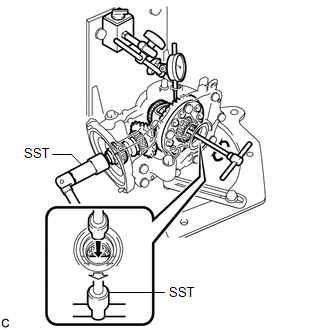
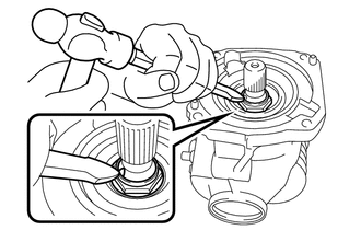
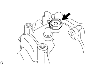
32. INSTALL REAR DRIVE PINION NUT
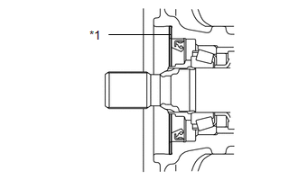
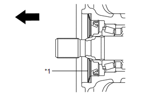
| (a) Using a chisel and a hammer, stake the rear drive pinion nut as shown in the illustration. |
|
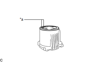
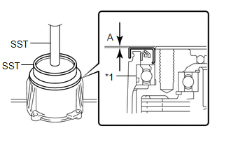
33. INSTALL DIAPHRAGM OIL SEAL
| (a) Using SST and a press, install a new diaphragm oil seal into the rear differential carrier assembly. SST: 09506-35010 SST: 09554-22010 NOTICE:
Standard Distance (A): 0.7 to 1.3 mm (0.0276 to 0.0511 in.) |
|
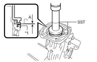
(b) Apply a light coat of MP grease to the lip of the new diaphragm oil seal.
34. INSTALL REAR DRIVE SHAFT OIL SEAL LH
| (a) Using SST and a press, install a new rear drive shaft oil seal LH into the differential side bearing retainer. SST: 09223-46011 SST: 09631-32020 NOTICE:
Standard Distance (A): 8.2 to 8.8 mm (0.323 to 0.346 in.) |
|
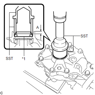
(b) Apply a light coat of MP grease to the lip of the new rear drive shaft oil seal LH.
35. INSTALL REAR DRIVE SHAFT OIL SEAL RH
| (a) Using SST and a press, install a new rear drive shaft oil seal RH into the rear differential carrier. SST: 09223-46011 SST: 09631-32020 NOTICE:
Standard Distance (A): 8.2 to 8.8 mm (0.323 to 0.346 in.) |
|
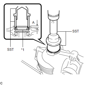
(b) Apply a light coat of MP grease to the lip of the new rear drive shaft oil seal RH.
36. INSTALL TRANSMISSION COUPLING SPACER
| (a) Install the transmission coupling spacer to the rear differential carrier assembly. NOTICE: Keep the transmission coupling spacer free of oil and foreign matter. |
|
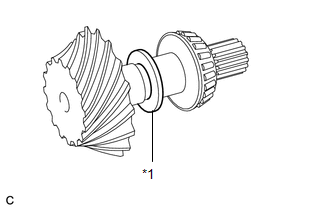
37. INSTALL TRANSMISSION COUPLING CONICAL SPRING WASHER
(a) Install the transmission coupling conical spring washer to the rear differential carrier assembly as shown in the illustration.
| *1 | Transmission Coupling Conical Spring Washer |
 | Front of the vehicle |
NOTICE:
Keep the transmission coupling conical spring washer free of oil and foreign matter.
HINT:
Make sure that the concave side is facing the front of the vehicle.
38. INSTALL REAR DIFFERENTIAL DUST DEFLECTOR
| (a) Align the matchmarks on the rear differential dust deflector and electro magnetic control coupling sub-assembly, and temporarily install the rear differential dust deflector. |
|
| (b) Using SST and a press, install the rear differential dust deflector. SST: 09223-15030 SST: 09950-70010 09951-07150 Standard Distance (A): 0 to 0.6 mm (0 to 0.0236 in.) NOTICE:
HINT: If the end surface of the electro magnetic control coupling sub-assembly is damaged while installing the rear differential dust deflector, replace the electro magnetic control coupling sub-assembly with a new one. |
|
39. INSTALL ELECTRO MAGNETIC CONTROL COUPLING SUB-ASSEMBLY
(a) Using a scraper and wire brush, remove the seal packing from the rear differential carrier assembly and electro magnetic control coupling sub-assembly.
NOTICE:
- Do not damage the contact surface.
- Be sure to completely remove all seal packing from the rear differential carrier assembly and electro magnetic control coupling sub-assembly.
- Do not allow the removed seal packing to enter the rear differential carrier assembly and electro magnetic control coupling sub-assembly.
(b) Using a non-residue solvent, remove grease and oil from the contact surfaces of the rear differential carrier assembly and the electro magnetic control coupling sub-assembly.
NOTICE:
Do not damage the contact surface.
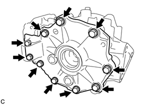
| (c) Apply seal packing to the areas indicated in the illustration of the rear differential carrier assembly. Seal Packing: Toyota Genuine Seal Packing 1281, Three Bond 1281 or equivalent NOTICE:
|
|
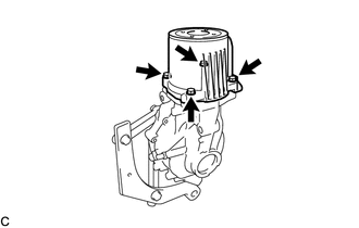
| (d) Install the electro magnetic control coupling sub-assembly with the 4 bolts. Torque: 19.6 N·m {200 kgf·cm, 14 ft·lbf} NOTICE:
|
|
40. INSTALL REAR DIFFERENTIAL CARRIER COVER BREATHER PLUG
| (a) Using a socket wrench, service nut and a hammer, install a new rear differential carrier cover breather plug to the rear differential carrier. HINT:
|
|
41. INSPECT RUNOUT OF ELECTRO MAGNETIC CONTROL COUPLING SUB-ASSEMBLY
(a) w/ LSD:
(1) Install a dial indicator and magnetic base perpendicular to the inner side of the electro magnetic control coupling sub-assembly as shown in the illustration.
| *1 | Rear Differential Case Assembly | - | - |
| *a | Vertical Runout | *b | Lateral Runout |
| *c | Urethane | - | - |
(2) Insert the urethane portion of SST until it reaches portion A shown in the illustration.
SST: 09564-52020
(3) Hold the B portion of SST and rotate the C portion, and continue expanding until the urethane portion of SST contacts the rear differential case assembly.
HINT:
If the urethane portion does not contact the rear differential case assembly, the rotation of SST and the rear differential case assembly will not be synchronized, and accurate measurement will be impossible.
(4) Using SST, rotate the electro magnetic control coupling sub-assembly forward and backward, and measure the vertical runout.
SST: 09564-52020
Maximum Runout:
0.06 mm (0.00236 in.)
If the runout is greater than the maximum value, replace the electro magnetic control coupling sub-assembly.
(5) Install a dial indicator and magnetic base perpendicular to the electro magnetic control coupling sub-assembly as shown in the illustration.
(6) Using SST, rotate the electro magnetic control coupling sub-assembly forward and backward, and measure the lateral runout.
SST: 09564-52020
Maximum Runout:
0.07 mm (0.00276 in.)
If the runout is greater than the maximum value, replace the electro magnetic control coupling sub-assembly.
(b) w/o LSD:
| (1) Install a dial indicator and magnetic base perpendicular to the inner side of the electro magnetic control coupling sub-assembly as shown in the illustration. |
|
(2) Using SST, rotate the electro magnetic control coupling sub-assembly forward and backward, and measure the vertical runout.
SST: 09564-32011
Maximum Runout:
0.06 mm (0.00236 in.)
If the runout is greater than the maximum value, replace the electro magnetic control coupling sub-assembly.
(3) Install a dial indicator and magnetic base perpendicular to the electro magnetic control coupling sub-assembly as shown in the illustration.
(4) Using SST, rotate the electro magnetic control coupling sub-assembly forward and backward, and measure the lateral runout.
SST: 09564-32011
Maximum Runout:
0.07 mm (0.00276 in.)
If the runout is greater than the maximum value, replace the electro magnetic control coupling sub-assembly.
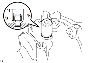
42. INSTALL STUD BOLT
| (a) Temporarily install 4 new stud bolts to the electro magnetic control coupling sub-assembly. NOTICE:
|
|
(b) Install 2 service nuts to the stud bolt.
Recommended Service Nut:
Thread Diameter
10 mm (0.394 in.)
Thread Pitch
1.0 mm (0.0394 in.)
HINT:
- Lock the upper nut using the lower nut.
- If the threads of the electro magnetic control coupling sub-assembly are damaged while installing the stud bolt, replace the electro magnetic control coupling sub-assembly with a new one.
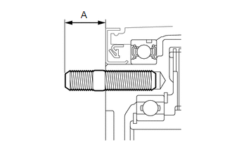
| (c) Turn the upper nut and tighten the other 3 stud bolts to the electro magnetic control coupling sub-assembly in the same way. Torque: 9.8 N·m {100 kgf·cm, 87 in·lbf} Standard Distance (A): 22.55 to 25.85 mm (0.888 to 1.017 in.) |
|
43. INSTALL REAR DIFFERENTIAL FILLER PLUG
| (a) Install a new gasket and the rear differential filler plug. Torque: 49 N·m {500 kgf·cm, 36 ft·lbf} |
|
44. INSTALL CONNECTOR BRACKET
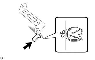
| (a) Install a new clamp to the connector bracket as shown in the illustration. |
|
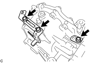
| (b) Install the 2 connector brackets with the 3 bolts. Torque: 19.6 N·m {200 kgf·cm, 14 ft·lbf} |
|
45. INSTALL ELECTRO MAGNETIC CONTROL COUPLING WIRE HARNESS
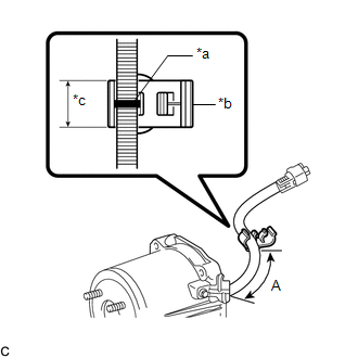
| (a) Install a new clamp to the electro magnetic control coupling wire harness as shown in the illustration. NOTICE: Be sure to align the clamp with the identification mark. Standard Distance (A): 76.5 to 82.5 mm (3.02 to 3.24 in.) |
|
| (b) Engage the claw to install the electro magnetic control coupling wire harness connector. |
|
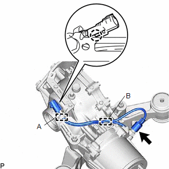
(c) Engage the electro magnetic control coupling wire harness to the clamp (A).
(d) Engage the clamp (B) to the connector bracket.
(e) Connect the temperature sensor connector.
NOTICE:
Do not damage the electro magnetic control coupling wire harness.
 Disassembly
DISASSEMBLY CAUTION / NOTICE / HINT NOTICE:
Before installation, thoroughly clean and dry each part and then apply Toyota Genuine Differential gear oil LX SAE 75W-85 GL-5 or equivalent to them...
 Installation
INSTALLATION PROCEDURE 1. INSTALL REAR DIFFERENTIAL SUPPORT (a) Install the differential support to the rear differential carrier assembly with 3 new bolts...
Other information:
Toyota Yaris XP210 (2020-2026) Reapir and Service Manual: Installation
INSTALLATION PROCEDURE 1. TEMPORARILY INSTALL AIR CONDITIONER UNIT ASSEMBLY (a) Temporarily install the air conditioner unit assembly to the instrument panel reinforcement assembly with the 3 bolts. 2. INSTALL INSTRUMENT PANEL REINFORCEMENT ASSEMBLY WITH AIR CONDITIONER UNIT ASSEMBLY (a) Engage the clamps...
Toyota Yaris XP210 (2020-2026) Reapir and Service Manual: Lost Communication with Front Left Air Mix Damper Control Servo Motor LIN Missing Message (B144B87)
DESCRIPTION The air conditioning harness assembly connects the air conditioning amplifier assembly and the No. 1 air conditioning radiator damper servo sub-assembly. The air conditioning amplifier assembly supplies power and sends operation instructions to No...
Categories
- Manuals Home
- Toyota Yaris Owners Manual
- Toyota Yaris Service Manual
- Fuse Panel Description
- Engine Start Function When Key Battery is Dead
- Power Integration No.1 System Missing Message (B235287,B235587,B235787-B235987)
- New on site
- Most important about car
Fuel-Filler Lid and Cap
WARNING
When removing the fuel-filler cap, loosen the cap slightly and wait for any hissing to stop, then remove it
Fuel spray is dangerous. Fuel can burn skin and eyes and cause illness if ingested. Fuel spray is released when there is pressure in the fuel tank and the fuel-filler cap is removed too quickly.