Toyota Yaris: Switch Housing / Installation
INSTALLATION
PROCEDURE
1. INSTALL STEERING WHEEL SWITCH HOUSING
(a) When reusing the steering wheel switch housing:
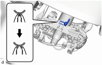
| (1) Using pliers, expand the clamp and temporarily install the steering wheel switch housing as shown in the illustration. |
|
.png)
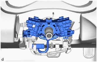
(2) While holding the clamp expanded, engage the claw to install the steering wheel switch housing as shown in the illustration.

.png) | Install in this Direction |
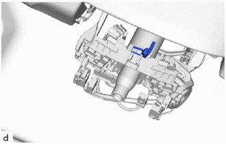
| (3) Release the clamp as shown in the illustration. |
|
(b) When installing a new steering wheel switch housing:
| (1) Temporarily install the steering wheel switch housing. |
|
(2) Engage the claw to install the steering wheel switch housing as shown in the illustration.
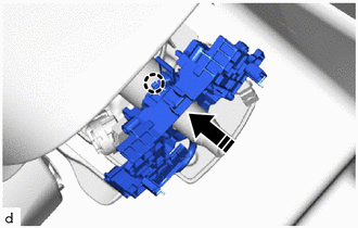
|
| Install in this Direction |
| (3) Remove the pin and release the clamp. |
|
2. INSTALL TURN SIGNAL SWITCH
Click here
.gif)
3. INSTALL WINDSHIELD WIPER SWITCH ASSEMBLY
Click here
4. INSTALL SPIRAL CABLE SUB-ASSEMBLY
Click here
 Removal
REMOVAL CAUTION / NOTICE / HINT HINT: When the cable is disconnected / reconnected to the auxiliary battery terminal, systems temporarily stop operating...
 Mirror (ext)
..
Other information:
Toyota Yaris XP210 (2020-2026) Reapir and Service Manual: Throttle / Pedal Position Sensor / Switch "A" Circuit Voltage Out of Range (P01201C)
DESCRIPTION Refer to DTC P012011. Click here DTC No. Detection Item DTC Detection Condition Trouble Area MIL Note P01201C Throttle / Pedal Position Sensor / Switch "A" Circuit Voltage Out of Range The difference between the output voltage of VTA1 and VTA2 is below 0...
Toyota Yaris XP210 (2020-2026) Reapir and Service Manual: Utility
U..
Categories
- Manuals Home
- Toyota Yaris Owners Manual
- Toyota Yaris Service Manual
- Fuse Panel Description
- Adjustment
- Brake System Control Module "A" System Voltage System Voltage Low (C137BA2)
- New on site
- Most important about car
Turning the Engine Off
Stop the vehicle completely. Manual transaxle: Shift into neutral and set the parking brake.Automatic transaxle: Shift the selector lever to the P position and set the parking brake.
Press the push button start to turn off the engine. The ignition position is off.