Toyota Yaris: Sfi System / Throttle / Pedal Position Sensor / Switch "A" Circuit Voltage Out of Range (P01201C)
DESCRIPTION
Refer to DTC P012011.
Click here

| DTC No. | Detection Item | DTC Detection Condition | Trouble Area | MIL | Note |
|---|---|---|---|---|---|
| P01201C | Throttle / Pedal Position Sensor / Switch "A" Circuit Voltage Out of Range | The difference between the output voltage of VTA1 and VTA2 is below 0.8 V, or higher than 1.6 V for less than 2 seconds (1 trip detection logic). |
| Comes on | SAE: P0121 |
MONITOR DESCRIPTION
The ECM uses the throttle position sensor to monitor the throttle valve opening angle. There are several checks that the ECM performs to confirm the proper operation of the throttle position sensor.
This sensor transmits two signals: VTA1 and VTA2. VTA1 is used to detect the throttle opening angle and VTA2 is used to detect malfunctions in VTA1. The ECM performs several checks to confirm the proper operation of the throttle position sensor and VTA1.
For each throttle opening angle, a specific voltage difference is expected between the outputs of VTA1 and VTA2. If the output voltage difference between the two signals deviates from the normal operating range, the ECM interprets this as a malfunction of the throttle position sensor, illuminates the MIL and stores a DTC.
MONITOR STRATEGY
| Frequency of Operation | Continuous |
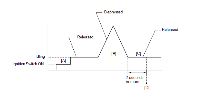
CONFIRMATION DRIVING PATTERN
- Connect the GTS to the DLC3.
- Turn the ignition switch to ON.
- Turn the GTS on.
- Clear the DTCs (even if no DTCs are stored, perform the clear DTC procedure).
- Turn the ignition switch off and wait for at least 30 seconds.
- Turn the ignition switch to ON [A].
- Turn the GTS on.
- Start the engine.
- With the vehicle stationary, fully depress and release the accelerator pedal [B].
- Idle the engine for 2 seconds or more [C].
- Enter the following menus: Powertrain / Engine / Trouble Codes [D].
-
Read the pending DTCs.
HINT:
- If a pending DTC is output, the system is malfunctioning.
- If a pending DTC is not output, perform the following procedure.
- Enter the following menus: Powertrain / Engine / Utility / All Readiness.
- Input the DTC: P01201C.
-
Check the DTC judgment result.
GTS Display
Description
NORMAL
- DTC judgment completed
- System normal
ABNORMAL
- DTC judgment completed
- System abnormal
INCOMPLETE
- DTC judgment not completed
- Perform driving pattern after confirming DTC enabling conditions
HINT:
- If the judgment result is NORMAL, the system is normal.
- If the judgment result is ABNORMAL, the system is malfunctioning.
- If the judgment result is INCOMPLETE, perform steps [B] through [D] again.
FAIL-SAFE
When this DTC is stored, the ECM enters fail-safe mode. During fail-safe mode, the ECM cuts the current to the throttle actuator, and the throttle valve is returned to a 7.5° throttle valve opening angle by the return spring. The ECM then adjusts the engine output by controlling the fuel injection (intermittent fuel-cut) and ignition timing, in accordance with the accelerator pedal angle, to allow the vehicle to continue running at a minimal speed. If the accelerator pedal is depressed firmly and gently, the vehicle can be driven slowly.
Fail-safe mode continues until a pass condition is detected, and the ignition switch is turned off.
WIRING DIAGRAM
Refer to DTC P012011.
Click here

CAUTION / NOTICE / HINT
HINT:
-
DTC P01201C is stored when the VTA1 and VTA2 output voltages are not consistent with the sensor characteristics. Therefore, check the Freeze Frame Data for this DTC. Use the following formula to confirm the relative differences in voltage.
Characteristic Sensor Output:
VTA2 x 0.8 is approximately equal to VTA1 + 1.11 V
VTA1: Throttle Position Sensor No.1 Voltage
VTA2: Throttle Position Sensor No.2 Voltage
- Read Freeze Frame Data using the GTS. The ECM records vehicle and driving condition information as Freeze Frame Data the moment a DTC is stored. When troubleshooting, Freeze Frame Data can help determine if the vehicle was moving or stationary, if the engine was warmed up or not, if the air fuel ratio was lean or rich, and other data from the time the malfunction occurred.
PROCEDURE
| 1. | CHECK HARNESS AND CONNECTOR (THROTTLE POSITION SENSOR - ECM) |
(a) Disconnect the throttle body with motor assembly connector.
(b) Disconnect the ECM connector.
(c) Measure the resistance according to the value(s) in the table below.
Standard Resistance:
| Tester Connection | Condition | Specified Condition |
|---|---|---|
| D19-5(VC) - D104-109(VCTA) | Always | Below 1 Ω |
| D19-6(VTA) - D104-108(VTA1) | Always | Below 1 Ω |
| D19-4(VTA2) - D104-87(VTA2) | Always | Below 1 Ω |
| D19-3(E2) - D104-110(ETA) | Always | Below 1 Ω |
| D19-5(VC) or D104-109(VCTA) - Body ground and other terminals | Always | 10 kΩ or higher |
| D19-6(VTA) or D104-108(VTA1) - Body ground and other terminals | Always | 10 kΩ or higher |
| D19-4(VTA2) or D104-87(VTA2) - Body ground and other terminals | Always | 10 kΩ or higher |
(d) Inspect the condition of the terminals of the connectors.
HINT:
Click here

| OK |
 | GO TO STEP 5 |
|

| 2. | REPAIR OR REPLACE HARNESS OR CONNECTOR |
(a) Repair or replace the wire harness or connector.
|

| 3. | CLEAR DTC |
(a) Clear the DTCs.
Powertrain > Engine > Clear DTCs(b) Turn the ignition switch off and wait for at least 30 seconds.
|

| 4. | CHECK WHETHER DTC OUTPUT RECURS (DTC P01201C) |
(a) Drive the vehicle in accordance with the driving pattern described in Confirmation Driving Pattern.
(b) Read the DTCs.
Powertrain > Engine > Trouble Codes| Result | Proceed to |
|---|---|
| DTCs are not output | A |
| P01201C is output | B |
| A |
 | END |
|

| 5. | CHECK HARNESS AND CONNECTOR (RESISTANCE OF ECM) |
(a) Disconnect the throttle body with motor assembly connector.
(b) Measure the resistance according to the value(s) in the table below.
Standard Resistance:
| Tester Connection | Condition | Specified Condition |
|---|---|---|
| D19-5(VC) - D19-6(VTA) | Ignition switch off | 190 to 210 kΩ |
| D19-5(VC) - D19-4(VTA2) | Ignition switch off | 190 to 210 kΩ |
| OK |
 | REPLACE THROTTLE BODY WITH MOTOR ASSEMBLY |
| NG |
 | REPLACE ECM |
 Throttle / Pedal Position Sensor / Switch "A" Circuit Short to Ground (P012011)
DESCRIPTION The throttle position sensor is built into the throttle body with motor assembly and detects the opening angle of the throttle valve. This sensor is a non-contact type sensor...
 Throttle / Pedal Position Sensor / Switch "A" Circuit Short to Battery or Open (P012015)
DESCRIPTION Refer to DTC P012011. Click here
DTC No. Detection Item DTC Detection Condition Trouble Area MIL Note P012015 Throttle / Pedal Position Sensor / Switch "A" Circuit Short to Battery or Open The output voltage of VTA1 is higher than 4...
Other information:
Toyota Yaris XP210 (2020-2025) Reapir and Service Manual: Problem Symptoms Table
PROBLEM SYMPTOMS TABLE NOTICE: If the auxiliary battery voltage becomes low, auxiliary battery load control will operate in order to ensure sufficient power is supplied to the power steering system. In this case, the window defogger system may not operate...
Toyota Yaris XP210 (2020-2025) Reapir and Service Manual: Components
COMPONENTS ILLUSTRATION *1 RING PIN *2 STRAIGHT PIN *3 STUD BOLT *4 NO. 3 OIL NOZZLE SUB-ASSEMBLY *5 NO. 2 OIL NOZZLE SUB-ASSEMBLY *6 NO. 1 OIL NOZZLE SUB-ASSEMBLY *7 PISTON PIN *8 PISTON RING SET *9 CRANKSHAFT BEARING *10 CRANKSHAFT *11 CRANKSHAFT THRUST WASHER *12 CRANKSHAFT BEARING CAP *13 CONNECTING ROD BEARING *14 CONNECTING ROD SUB-ASSEMBLY *15 CONNECTING ROD BEARING CAP *16 CYLINDER BLOCK INSURATOR *17 NO...
Categories
- Manuals Home
- Toyota Yaris Owners Manual
- Toyota Yaris Service Manual
- Engine & Hybrid System
- Adjustment
- How to connect USB port/Auxiliary jack
- New on site
- Most important about car
Turning the Engine Off
Stop the vehicle completely. Manual transaxle: Shift into neutral and set the parking brake.Automatic transaxle: Shift the selector lever to the P position and set the parking brake.
Press the push button start to turn off the engine. The ignition position is off.