Toyota Yaris: Sfi System / Throttle / Pedal Position Sensor / Switch "A" Circuit Short to Ground (P012011)
DESCRIPTION
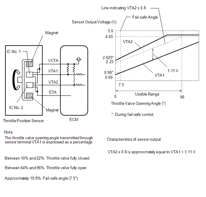
The throttle position sensor is built into the throttle body with motor assembly and detects the opening angle of the throttle valve. This sensor is a non-contact type sensor. It uses Hall-effect elements in order to yield accurate signals even in extreme driving conditions, such as at high speeds as well as very low speeds.
The throttle position sensor has 2 sensor circuits, VTA1 and VTA2, each of which transmits a signal. VTA1 is used to detect the throttle valve angle and VTA2 is used to detect malfunctions in VTA1. The sensor signal voltages vary between 0 V and 5 V in proportion to the throttle valve opening angle, and are transmitted to the VTA1 and VTA2 terminals of the ECM.
As the valve closes, the sensor output voltage decreases and as the valve opens, the sensor output voltage increases. The ECM calculates the throttle valve opening angle according to these signals and controls the throttle actuator in response to driver inputs. These signals are also used in calculations such as air fuel ratio correction, power increase correction and fuel-cut control.
HINT:
- When throttle position sensor DTCs are output, check the throttle valve opening angle using the GTS. Enter the following menus: Powertrain / Engine / Data List / Throttle Position Sensor No.1 Voltage and Throttle Position Sensor No.2 Voltage.
-
Throttle Position Sensor No.1 Voltage is the VTA1 signal, and Throttle Position Sensor No.2 Voltage is the VTA2 signal.
Reference (Normal Condition):
When Accelerator Pedal Fully Released
When Accelerator Pedal Fully Depressed
(Engine Running)
Throttle Position Sensor No.1 Voltage (VTA1)
Throttle Position Sensor No.2 Voltage (VTA2)
Throttle Position Sensor No.1 Voltage (VTA1)
Throttle Position Sensor No.2 Voltage (VTA2)
0.6 to 1.1 V
2.1 to 3.1 V
3.2 to 4.8 V
(Not fail-safe)
4.6 to 4.98 V
(Not fail-safe)
| DTC No. | Detection Item | DTC Detection Condition | Trouble Area | MIL | Note |
|---|---|---|---|---|---|
| P012011 | Throttle / Pedal Position Sensor / Switch "A" Circuit Short to Ground | The output voltage of VTA1 is below 0.56 V for 2 seconds or more (1 trip detection logic). |
| Comes on | SAE: P0122 |
MONITOR DESCRIPTION
The ECM uses the throttle position sensor to monitor the throttle valve opening angle. If the VTA1 terminal voltage is less than the threshold, the ECM will illuminate the MIL and store this DTC.
MONITOR STRATEGY
| Frequency of Operation | Continuous |
CONFIRMATION DRIVING PATTERN
- Connect the GTS to the DLC3.
- Turn the ignition switch to ON.
- Turn the GTS on.
- Clear the DTCs (even if no DTCs are stored, perform the clear DTC procedure).
- Turn the ignition switch off and wait for at least 30 seconds.
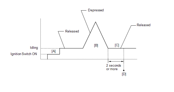
- Turn the ignition switch to ON [A].
- Turn the GTS on.
- Start the engine.
- With the vehicle stationary, fully depress and release the accelerator pedal [B].
- Idle the engine for 2 seconds or more [C].
- Enter the following menus: Powertrain / Engine / Trouble Codes [D].
-
Read the pending DTCs.
HINT:
- If a pending DTC is output, the system is malfunctioning.
- If a pending DTC is not output, perform the following procedure.
- Enter the following menus: Powertrain / Engine / Utility / All Readiness.
- Input the DTC: P012011.
-
Check the DTC judgment result.
GTS Display
Description
NORMAL
- DTC judgment completed
- System normal
ABNORMAL
- DTC judgment completed
- System abnormal
INCOMPLETE
- DTC judgment not completed
- Perform driving pattern after confirming DTC enabling conditions
HINT:
- If the judgment result is NORMAL, the system is normal.
- If the judgment result is ABNORMAL, the system is malfunctioning.
- If the judgment result is INCOMPLETE, perform steps [B] through [D] again.
FAIL-SAFE
When this DTC is stored, the ECM enters fail-safe mode. During fail-safe mode, the ECM cuts the current to the throttle actuator, and the throttle valve is returned to a 7.5° throttle valve opening angle by the return spring. The ECM then adjusts the engine output by controlling the fuel injection (intermittent fuel-cut) and ignition timing, in accordance with the accelerator pedal angle, to allow the vehicle to continue running at a minimal speed. If the accelerator pedal is depressed firmly and gently, the vehicle can be driven slowly.
Fail-safe mode continues until a pass condition is detected, and the ignition switch is turned off.
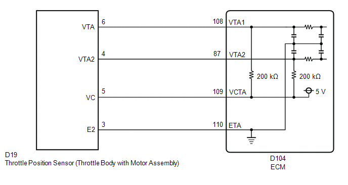
WIRING DIAGRAM
CAUTION / NOTICE / HINT
HINT:
Read Freeze Frame Data using the GTS. The ECM records vehicle and driving condition information as Freeze Frame Data the moment a DTC is stored. When troubleshooting, Freeze Frame Data can help determine if the vehicle was moving or stationary, if the engine was warmed up or not, if the air fuel ratio was lean or rich, and other data from the time the malfunction occurred.
PROCEDURE
| 1. | READ VALUE USING GTS (THROTTLE POSITION SENSOR NO.1 VOLTAGE) |
(a) Read the values displayed on the GTS.
Powertrain > Engine > Data List| Tester Display |
|---|
| Throttle Position Sensor No.1 Voltage |
(b) Disconnect the throttle body with motor assembly connector.
(c) Compare the value of the Data List item Throttle Position Sensor No.1 Voltage after disconnecting the throttle body with motor assembly connector to the value when the connector was connected.
| Result | Proceed to |
|---|---|
| Changes from below 0.56 V to higher than 4.535 V | A |
| Does not change from below 0.56 V | B |
| A |
 | REPLACE THROTTLE BODY WITH MOTOR ASSEMBLY |
|

| 2. | CHECK HARNESS AND CONNECTOR (THROTTLE POSITION SENSOR - ECM) |
(a) Disconnect the throttle body with motor assembly connector.
(b) Disconnect the ECM connector.
(c) Measure the resistance according to the value(s) in the table below.
Standard Resistance:
| Tester Connection | Condition | Specified Condition |
|---|---|---|
| D19-5(VC) - D104-109(VCTA) | Always | Below 1 Ω |
| D19-6(VTA) or D104-108(VTA1) - Body ground | Always | 10 kΩ or higher |
| OK |
 | REPLACE ECM |
| NG |
 | REPAIR OR REPLACE HARNESS OR CONNECTOR |
 Engine Coolant Temperature Sensor 1 Circuit Short to Battery or Open (P011515)
DESCRIPTION Refer to DTC P011511. Click here
HINT: When DTC P011515 is stored, the ECM enters fail-safe mode. During fail-safe mode, the ECM sets the engine coolant temperature judgment value to 80°C (176°F) and the target engine coolant temperature to 82°C (180°F)...
 Throttle / Pedal Position Sensor / Switch "A" Circuit Voltage Out of Range (P01201C)
DESCRIPTION Refer to DTC P012011. Click here
DTC No. Detection Item DTC Detection Condition Trouble Area MIL Note P01201C Throttle / Pedal Position Sensor / Switch "A" Circuit Voltage Out of Range The difference between the output voltage of VTA1 and VTA2 is below 0...
Other information:
Toyota Yaris XP210 (2020-2025) Reapir and Service Manual: Disassembly
DISASSEMBLY PROCEDURE 1. REMOVE ACTIVE NOISE CONTROL MICROPHONE (w/ Active Noise Control System) Click here 2. REMOVE ROOF HEADLINING HOLDER COVER (w/ Active Noise Control System) HINT: Use the same procedure for the opposite side. (a) Disengage the claws to remove the roof headlining holder cover...
Toyota Yaris XP210 (2020-2025) Reapir and Service Manual: Operation Check
OPERATION CHECK CHECK CUSTOMIZE PARAMETERS NOTICE: The operation check below is based on the non-customized initial condition of the vehicle. Click here HINT: The switches described in this text are the switches for transmitting signals. The switches are built into the electrical key transmitter sub-assembly...
Categories
- Manuals Home
- Toyota Yaris Owners Manual
- Toyota Yaris Service Manual
- G16e-gts (engine Mechanical)
- Removal
- Battery Monitor Module General Electrical Failure (P058A01)
- New on site
- Most important about car
Supplemental Restraint System (SRS) Precautions
The front and side supplemental restraint systems (SRS) include different types of air bags. Please verify the different types of air bags which are equipped on your vehicle by locating the “SRS AIRBAG” location indicators. These indicators are visible in the area where the air bags are installed.
The air bags are installed in the following locations:
The steering wheel hub (driver air bag) The front passenger dashboard (front passenger air bag) The outboard sides of the front seatbacks (side air bags) The front and rear window pillars, and the roof edge along both sides (curtain air bags)