Toyota Yaris: Sfi System / Engine Coolant Temperature Sensor 1 Circuit Short to Battery or Open (P011515)
DESCRIPTION
Refer to DTC P011511.
Click here

HINT:
When DTC P011515 is stored, the ECM enters fail-safe mode. During fail-safe mode, the ECM sets the engine coolant temperature judgment value to 80°C (176°F) and the target engine coolant temperature to 82°C (180°F). Fail-safe mode continues until a pass condition is detected.
| DTC No. | Detection Item | DTC Detection Condition | Trouble Area | MIL | Note |
|---|---|---|---|---|---|
| P011515 | Engine Coolant Temperature Sensor 1 Circuit Short to Battery or Open | The engine coolant temperature sensor output voltage is higher than 4.91 V for 0.5 seconds or more (1 trip detection logic). |
| Comes on | SAE: P0118 |
HINT:
When a DTC is output, check the Data List item "Coolant Temperature" using the GTS.
Click here

| DTC No. | Coolant Temperature | Malfunction |
|---|---|---|
| P011515 | -40°C (-40°F) |
|
If the Data List displays a normal value, the normal value may be due to a temporary recovery from the malfunction condition. Check for intermittent problems.
MONITOR DESCRIPTION
The engine coolant temperature sensor is used to monitor the outlet side engine coolant temperature. The engine coolant temperature sensor has a thermistor with a resistance that varies according to the temperature of the engine coolant. When the engine coolant temperature is low, the resistance in the thermistor increases. When the temperature is high, the resistance decreases. These variations in resistance are reflected in the output voltage from the sensor. The ECM monitors the sensor voltage and uses this value to calculate the engine coolant temperature. If the engine coolant temperature sensor output voltage deviates from the normal operating range, the ECM interprets this as a malfunction in the engine coolant temperature sensor circuit, illuminates the MIL and stores a DTC.
Example:
If the engine coolant temperature sensor output voltage is higher than 4.91 V for 0.5 seconds or more, the ECM will illuminate the MIL and store this DTC.
MONITOR STRATEGY
| Frequency of Operation | Continuous |
CONFIRMATION DRIVING PATTERN
- Connect the GTS to the DLC3.
- Turn the ignition switch to ON.
- Turn the GTS on.
- Clear the DTCs (even if no DTCs are stored, perform the clear DTC procedure).
- Turn the ignition switch off and wait for at least 30 seconds.
- Turn the ignition switch to ON.
- Turn the GTS on.
- Wait 5 seconds or more.
- Enter the following menus: Powertrain / Engine / Trouble Codes.
-
Read the pending DTCs.
HINT:
- If a pending DTC is output, the system is malfunctioning.
- If a pending DTC is not output, perform the following procedure.
- Enter the following menus: Powertrain / Engine / Utility / All Readiness.
- Input the DTC: P011515.
-
Check the DTC judgment result.
GTS Display
Description
NORMAL
- DTC judgment completed
- System normal
ABNORMAL
- DTC judgment completed
- System abnormal
INCOMPLETE
- DTC judgment not completed
- Perform driving pattern after confirming DTC enabling conditions
HINT:
- If the judgment result is NORMAL, the system is normal.
- If the judgment result is ABNORMAL, the system is malfunctioning.
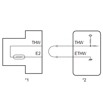
WIRING DIAGRAM
Refer to DTC P011511.
Click here

CAUTION / NOTICE / HINT
HINT:
Read Freeze Frame Data using the GTS. The ECM records vehicle and driving condition information as Freeze Frame Data the moment a DTC is stored. When troubleshooting, Freeze Frame Data can help determine if the vehicle was moving or stationary, if the engine was warmed up or not, if the air fuel ratio was lean or rich, and other data from the time the malfunction occurred.
PROCEDURE
| 1. | READ VALUE USING GTS (CHECK FOR OPEN IN WIRE HARNESS) |
| (a) Disconnect the engine coolant temperature sensor connector. |
|
(b) Connect terminals 1 (E2) and 2 (THW) of the engine coolant temperature sensor connector on the wire harness side.
(c) Enter the following menus.
Powertrain > Engine > Data List| Tester Display |
|---|
| Coolant Temperature |
(d) According to the display on the GTS, read the Data List.
OK:
| GTS Display | Specified Condition |
|---|---|
| Coolant Temperature | Higher than 135°C (275°F) |
HINT:
Perform "Inspection After Repair" after replacing the engine coolant temperature sensor.
Click here

| OK |
 | REPLACE ENGINE COOLANT TEMPERATURE SENSOR |
|

| 2. | CHECK HARNESS AND CONNECTOR (ENGINE COOLANT TEMPERATURE SENSOR - ECM) |
(a) Disconnect the engine coolant temperature sensor connector.
(b) Disconnect the ECM connector.
(c) Measure the resistance according to the value(s) in the table below.
Standard Resistance:
| Tester Connection | Condition | Specified Condition |
|---|---|---|
| D35-2(THW) - D104-129(THW) | Always | Below 1 Ω |
| D35-1(E2) - D104-130(ETHW) | Always | Below 1 Ω |
| D35-2(THW) or D104-129(THW) - Other terminals | Always | 10 kΩ or higher |
| OK |
 | REPLACE ECM |
| NG |
 | REPAIR OR REPLACE HARNESS OR CONNECTOR |
 Engine Coolant Temperature Sensor 1 Signal Stuck in Range (P01152A)
DESCRIPTION Refer to DTC P011511. Click here
DTC No. Detection Item DTC Detection Condition Trouble Area MIL Note P01152A Engine Coolant Temperature Sensor 1 Signal Stuck in Range Either of the following conditions is met (2 trip detection logic):
When engine is started cold and warmed up, the engine coolant temperature sensor value does not change...
 Throttle / Pedal Position Sensor / Switch "A" Circuit Short to Ground (P012011)
DESCRIPTION The throttle position sensor is built into the throttle body with motor assembly and detects the opening angle of the throttle valve. This sensor is a non-contact type sensor...
Other information:
Toyota Yaris XP210 (2020-2025) Reapir and Service Manual: Problem Symptoms Table
PROBLEM SYMPTOMS TABLE HINT: If a problem occurs in certain locations or at certain times of day, check for the possibility of wave interference. When the electrical key transmitter sub-assembly is brought near a smart door control receiver assembly (RF band), door outside handle assembly (LF band), indoor electrical key antenna (LF band) or any of the electrical key antennas (LF band), the possibility of wave interference decreases...
Toyota Yaris XP210 (2020-2025) Reapir and Service Manual: Diagnosis System
DIAGNOSIS SYSTEM DESCRIPTION The main body ECU (multiplex network body ECU) and certification ECU (smart key ECU assembly) control the LIN communication system. LIN communication system data and Diagnostic Trouble Codes (DTCs) can be read through the Data Link Connector 3 (DLC3)...
Categories
- Manuals Home
- Toyota Yaris Owners Manual
- Toyota Yaris Service Manual
- Key Battery Replacement
- Power Integration No.1 System Missing Message (B235287,B235587,B235787-B235987)
- To Set Speed
- New on site
- Most important about car
Break-In Period
No special break-in is necessary, but a few precautions in the first 600 miles (1,000 km) may add to the performance, economy, and life of the vehicle.
Do not race the engine. Do not maintain one constant speed, either slow or fast, for a long period of time. Do not drive constantly at full-throttle or high engine rpm for extended periods of time. Avoid unnecessary hard stops. Avoid full-throttle starts.