Toyota Yaris: Stop And Start System / System Diagram
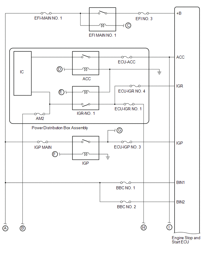
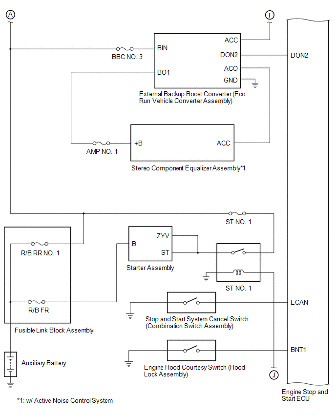
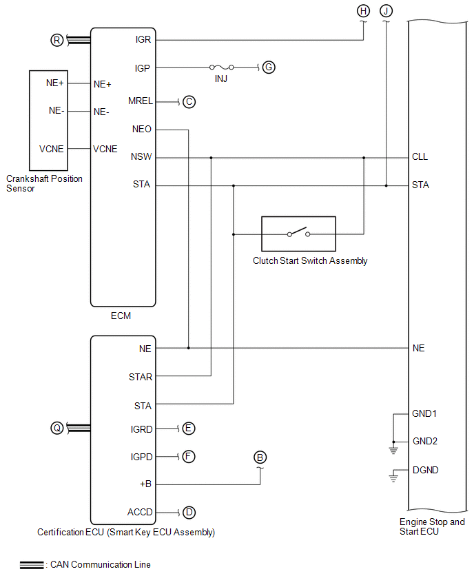
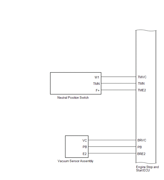
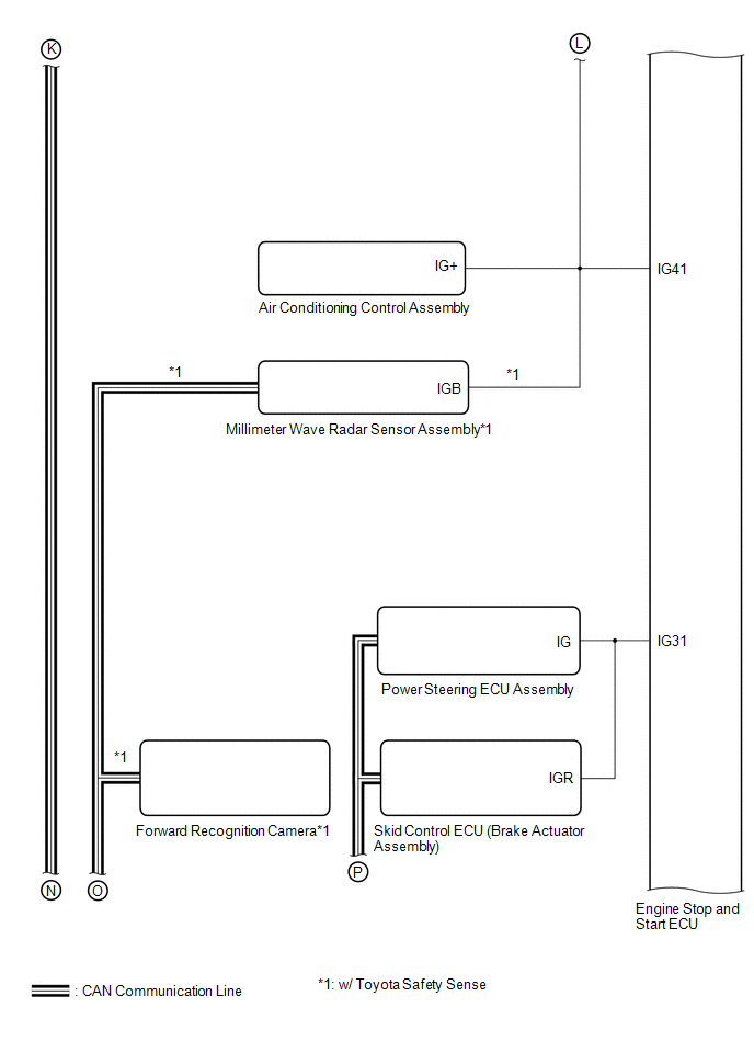
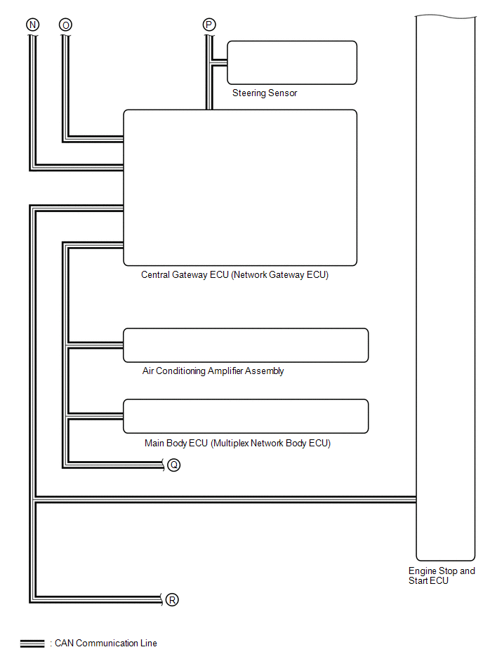
SYSTEM DIAGRAM

 Parts Location
PARTS LOCATION ILLUSTRATION
*A w/ Toyota Safety Sense *B w/ Active Noise Control System *1 ENGINE HOOD COURTESY SWITCH (HOOD LOCK ASSEMBLY) *2 VACUUM SENSOR ASSEMBLY *3 INNER REAR VIEW MIRROR ASSEMBLY *4 ECM *5 SKID CONTROL ECU (BRAKE ACTUATOR ASSEMBLY) *6 EXTERNAL BACKUP BOOST CONVERTER (ECO RUN VEHICLE CONVERTER ASSEMBLY) *7 MILLIMETER WAVE RADAR SENSOR ASSEMBLY *8 FORWARD RECOGNITION CAMERA *9 ENGINE ROOM RELAY BLOCK - EFI-MAIN NO...
 System Description
SYSTEM DESCRIPTION STOP AND START CONTROL The stop and start system operates according to the following conditions, achieving appropriate engine stop and start control together with safe and smooth driving characteristics...
Other information:
Toyota Yaris XP210 (2020-2026) Reapir and Service Manual: Data List / Active Test
DATA LIST / ACTIVE TEST DATA LIST NOTICE: Some Data List values may vary significantly due to slight measurement errors, differences in the measurement environment, and changes in the vehicle over time, making it difficult to indicate clear evaluation standards...
Toyota Yaris XP210 (2020-2026) Owner's Manual: Fuel Consumption Display
Information regarding the fuel economy is displayed. Displays the fuel economy for the past 60 minutes. Displays the fuel economy every minute for the past 1 to 10 minutes. Displays the fuel economy every 10 minutes for the past 10 to 60 minutes...
Categories
- Manuals Home
- Toyota Yaris Owners Manual
- Toyota Yaris Service Manual
- How to use USB mode
- Power Integration No.1 System Missing Message (B235287,B235587,B235787-B235987)
- To Set Speed
- New on site
- Most important about car
Key Suspend Function
If a key is left in the vehicle, the functions of the key left in the vehicle are temporarily suspended to prevent theft of the vehicle.
To restore the functions, press the unlock button on the functions-suspended key in the vehicle.
Copyright © 2026 www.toyaris4.com