Toyota Yaris: Smart Key System (for Start Function) / Engine Immobiliser System Signal (Some Circuit Quantity, Reported via Serial Data) Invalid (B279986)
DESCRIPTION
If there is a communication malfunction between the ECM and ID code box (immobiliser code ECU), or when the communication ID codes do not match, the ECM stores this DTC.
| DTC No. | Detection Item | DTC Detection Condition | Trouble Area | Note |
|---|---|---|---|---|
| B279986 | Engine Immobiliser System Signal (Some Circuit Quantity, Reported via Serial Data) Invalid | Either of the following conditions is met (1 trip detection logic*):
|
| DTC output confirmation operation (Perform either of the following):
|
- *: Only output while a malfunction is present.
| Vehicle Condition when Malfunction Detected | Fail-safe Operation when Malfunction Detected |
|---|---|
| Engine cannot be started | - |
| DTC No. | Data List and Active Test |
|---|---|
| B279986 | - |
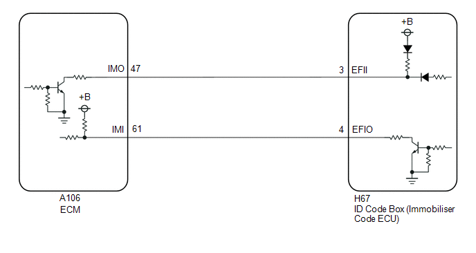
WIRING DIAGRAM
CAUTION / NOTICE / HINT
NOTICE:
- When using the GTS with the ignition switch off, connect the GTS to the DLC3 and turn a courtesy light switch on and off at intervals of 1.5 seconds or less until communication between the GTS and the vehicle begins. Then select the vehicle type under manual mode and enter the following menus: Body Electrical / Smart Key. While using the GTS, periodically turn a courtesy light switch on and off at intervals of 1.5 seconds or less to maintain communication between the GTS and the vehicle.
-
The smart key system (for Start Function) uses the LIN communication system and CAN communication system. Inspect the communication function by following How to Proceed with Troubleshooting. Troubleshoot the smart key system (for Start Function) after confirming that the communication systems are functioning properly.
Click here

-
Before replacing the ECM or ID code box (immobiliser code ECU), refer to Registration.
Click here

- After performing repairs, confirm that no DTCs are output by performing "DTC Output Confirmation Operation".
HINT:
When DTC B279986 and the certification ECU (smart key ECU assembly) DTC are output simultaneously, first perform troubleshooting for the certification ECU (smart key ECU assembly) DTC.
PROCEDURE
| 1. | REGISTER ECU COMMUNICATION ID |
(a) Register the ECU communication ID code.
Click here

|

| 2. | CHECK ID CODE BOX (IMMOBILISER CODE ECU) (TERMINAL EFII) |
(a) Using an oscilloscope, check the waveform.
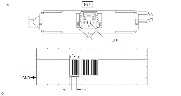
| *a | Component with harness connected (ID Code Box (Immobiliser Code ECU)) | *b | Waveform |
| *c | Approximately 160 ms. | *d | Approximately 270 ms. |
OK:
| Tester Connection | Condition | Tool Setting | Specified Condition |
|---|---|---|---|
| H67-3 (EFII) - Body ground | Within 3 seconds of the engine start operation being performed or within 3 seconds of the ignition switch being turned to ON after connecting the cable to the negative (-) auxiliary battery terminal | 2 V/DIV., 500 ms./DIV. | Pulse generation (See waveform) |
| Result | Proceed to |
|---|---|
| Normal waveform | A |
| Terminal EFII stuck low (2.4 V or less) | B |
| Waveform not output, or has abnormal wavelength or shape, or terminal EFII stuck high (12 V) | C |
| B |
 | GO TO STEP 6 |
| C |
 | GO TO STEP 8 |
|

| 3. | CHECK ID CODE BOX (IMMOBILISER CODE ECU) (TERMINAL EFIO) |
(a) Using an oscilloscope, check the waveform.
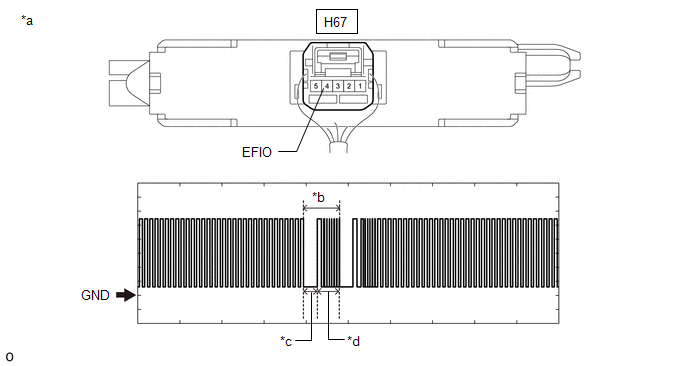
| *a | Component with harness connected (ID Code Box (Immobiliser Code ECU)) | *b | Waveform |
| *c | Approximately 160 ms. | *d | Approximately 270 ms. |
Measurement Condition:
| Tester Connection | Condition | Tool Setting | Specified Condition |
|---|---|---|---|
| H67-4 (EFIO) - Body ground | Within 3 seconds of the engine start operation being performed or within 3 seconds of the ignition switch being turned to ON after connecting the cable to the negative (-) auxiliary battery terminal | 2 V/DIV., 500 ms./DIV. | Pulse generation (See waveform) |
| NG |
 | REPLACE ID CODE BOX (IMMOBILISER CODE ECU) |
|

| 4. | REGISTER ECU COMMUNICATION ID (ID CODE BOX (IMMOBILISER CODE ECU) - ECM) |
(a) Register the ECU communication ID codes.
Click here

|

| 5. | CHECK WHETHER ENGINE STARTS |
(a) Using an electrical key transmitter sub-assembly which is registered to the vehicle, turn the ignition switch to ON.
(b) Check that the engine can be started 5 seconds after the ignition switch turned to ON.
OK:
Engine starts normally.
| OK |
 | END (ECU COMMUNICATION ID HAS NOT BEEN REGISTERED) |
| NG |
 | REPLACE ECM |
| 6. | CHECK ECM |
(a) Disconnect the A106 ECM connector.
(b) Measure the voltage according to the value(s) in the table below.
Standard Voltage:
| Tester Connection | Condition | Specified Condition |
|---|---|---|
| A106-47 (IMO) - Body ground | Ignition switch turned to ON using registered electrical key transmitter sub-assembly | Terminal IMO stuck low (2.4 V or less) |
| Terminal IMO stuck high (12 V) or abnormal waveform |
| Result | Proceed to |
|---|---|
| Terminal IMO stuck low (2.4 V or less) | A |
| Terminal IMO stuck high (12 V) or abnormal waveform | B |
| B |
 | REPLACE ECM |
|

| 7. | CHECK HARNESS AND CONNECTOR (ID CODE BOX (IMMOBILISER CODE ECU) - ECM) |
(a) Disconnect the H67 ID code box (immobiliser code ECU) connector.
(b) Measure the resistance according to the value(s) in the table below.
Standard Resistance:
| Tester Connection | Condition | Specified Condition |
|---|---|---|
| A106-47 (IMO) - H67-3 (EFII) | Always | Below 1 Ω |
| A106-47 (IMO) or H67-3 (EFII) - Other terminals and body ground | Always | 10 kΩ or higher |
| A106-61 (IMI) - H67-4 (EFIO) | Always | Below 1 Ω |
| A106-61 (IMI) or H67-4 (EFIO) - Other terminals and body ground | Always | 10 kΩ or higher |
| OK |
 | REPLACE ID CODE BOX (IMMOBILISER CODE ECU) |
| NG |
 | REPAIR OR REPLACE HARNESS OR CONNECTOR |
| 8. | CHECK HARNESS AND CONNECTOR (ID CODE BOX (IMMOBILISER CODE ECU) - ECM) |
(a) Disconnect the H67 ID code box (immobiliser code ECU) connector.
(b) Disconnect the A106 ECM connector.
(c) Measure the resistance according to the value(s) in the table below.
Standard Resistance:
| Tester Connection | Condition | Specified Condition |
|---|---|---|
| A106-47 (IMO) - H67-3 (EFII) | Always | Below 1 Ω |
| A106-47 (IMO) or H67-3 (EFII) - Other terminals and body ground | Always | 10 kΩ or higher |
| OK |
 | REPLACE ECM |
| NG |
 | REPAIR OR REPLACE HARNESS OR CONNECTOR |
 ID-BOX Calibration / Parameter Memory Failure (B279046)
DESCRIPTION When an internal malfunction occurs in the ID code box (immobiliser code ECU), the certification ECU (smart key ECU assembly) stores this DTC...
 Engine Immobiliser System Circuit Short to Battery (B279A12)
DESCRIPTION If the communication line (IMI - EFIO) between the ECM and ID code box (immobiliser code ECU) is stuck high, the ECM will store this DTC. DTC No...
Other information:
Toyota Yaris XP210 (2020-2025) Reapir and Service Manual: Problem Symptoms Table
PROBLEM SYMPTOMS TABLE HINT: Inspect the fuses and relays related to this system before inspecting the suspected areas below. Use the table below to help determine the cause of problem symptoms. If multiple suspected areas are listed, the potential causes of the symptoms are listed in order of probability in the "Suspected Area" column of the table...
Toyota Yaris XP210 (2020-2025) Reapir and Service Manual: Removal
REMOVAL CAUTION / NOTICE / HINT The necessary procedures (adjustment, calibration, initialization, or registration) that must be performed after parts are replaced during millimeter wave radar sensor assembly removal/installation are shown below. Necessary Procedure After Parts Removed/Installed/Replaced Replaced Part or Performed Procedure Necessary Procedure Effect/Inoperative Function when Necessary Procedure not Performed Link Millimeter wave radar sensor assembly Adjust millimeter wave radar sensor assembly Dynamic Radar Cruise Control System Lane Tracing Assist System Front Radar Sensor System Pre-collision System Auto High Beam System Triangle Target: Flat Surface Target: Driving Adjustment: Update ECU security key Vehicle control history (RoB) are stored PROCEDURE 1...
Categories
- Manuals Home
- Toyota Yaris Owners Manual
- Toyota Yaris Service Manual
- Diagnostic Trouble Code Chart
- G16e-gts (engine Mechanical)
- Engine Start Function When Key Battery is Dead
- New on site
- Most important about car
Supplemental Restraint System (SRS) Precautions
The front and side supplemental restraint systems (SRS) include different types of air bags. Please verify the different types of air bags which are equipped on your vehicle by locating the “SRS AIRBAG” location indicators. These indicators are visible in the area where the air bags are installed.
The air bags are installed in the following locations:
The steering wheel hub (driver air bag) The front passenger dashboard (front passenger air bag) The outboard sides of the front seatbacks (side air bags) The front and rear window pillars, and the roof edge along both sides (curtain air bags)