Toyota Yaris: Millimeter Wave Radar Sensor / Removal
REMOVAL
CAUTION / NOTICE / HINT
The necessary procedures (adjustment, calibration, initialization, or registration) that must be performed after parts are replaced during millimeter wave radar sensor assembly removal/installation are shown below.
Necessary Procedure After Parts Removed/Installed/Replaced| Replaced Part or Performed Procedure | Necessary Procedure | Effect/Inoperative Function when Necessary Procedure not Performed | Link |
|---|---|---|---|
| Millimeter wave radar sensor assembly | Adjust millimeter wave radar sensor assembly |
| Triangle Target:
Flat Surface Target:
Driving Adjustment:
|
| Update ECU security key | Vehicle control history (RoB) are stored |
|


PROCEDURE
1. REMOVE FRONT BUMPER ASSEMBLY
Click here

2. REMOVE MILLIMETER WAVE RADAR SENSOR ASSEMBLY
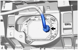
| (a) Disconnect the connector. |
|
(b) Remove the 2 bolts and screw.
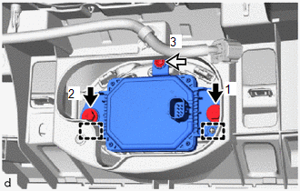
 | Bolt |
 | Screw |
(c) Disengage the guides to remove the millimeter wave radar sensor assembly.
NOTICE:
Do not reuse the millimeter wave radar sensor assembly if it has been dropped or subjected to a severe impact.
 Components
C..
 Installation
INSTALLATION PROCEDURE 1. INSTALL MILLIMETER WAVE RADAR SENSOR ASSEMBLY NOTICE: If the millimeter wave radar sensor assembly has been struck or dropped, replace the millimeter wave radar sensor assembly with a new one...
Other information:
Toyota Yaris XP210 (2020-2026) Reapir and Service Manual: Removal
REMOVAL CAUTION / NOTICE / HINT HINT: Use the same procedure for the RH and LH sides. The procedure listed below is for the LH side. PROCEDURE 1. REMOVE FRONT DOOR LOWER FRAME BRACKET GARNISH Click here 2. REMOVE MULTIPLEX NETWORK MASTER SWITCH ASSEMBLY WITH FRONT ARMREST BASE UPPER PANEL (for Driver Side) Click here 3...
Toyota Yaris XP210 (2020-2026) Reapir and Service Manual: Fuel Pump Control Circuit Current Out of Range (P12D41D)
DESCRIPTION Refer to DTC P062712. Click here DTC No. Detection Item DTC Detection Condition Trouble Area MIL Note P12D41D Fuel Pump Control Circuit Current Out of Range When the fuel pump control ECU operation duty ratio is 3 to 65%, overcurrent in the fuel pump circuit is detected for 3 seconds or more (1 trip detection logic)...
Categories
- Manuals Home
- Toyota Yaris Owners Manual
- Toyota Yaris Service Manual
- Diagnostic Trouble Code Chart
- G16e-gts (engine Mechanical)
- To Set Speed
- New on site
- Most important about car
Fuel Gauge
The fuel gauge shows approximately how much fuel is remaining in the tank when the ignition is switched ON. We recommend keeping the tank over 1/4 full.
