Toyota Yaris: Millimeter Wave Radar Sensor / Installation
INSTALLATION
PROCEDURE
1. INSTALL MILLIMETER WAVE RADAR SENSOR ASSEMBLY
NOTICE:
If the millimeter wave radar sensor assembly has been struck or dropped, replace the millimeter wave radar sensor assembly with a new one.
(a) Engage the guides to install the millimeter wave radar sensor assembly.
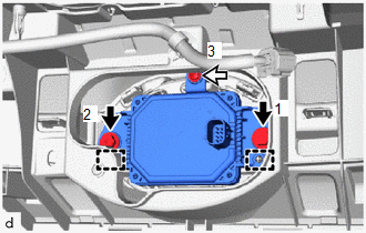
 | Bolt |
 | Screw |
(b) Install the 2 bolts and screw in the order shown in the illustration.
Torque:
Bolt :
4.5 N·m {46 kgf·cm, 40 in·lbf}
(c) Connect the connector.
2. INSTALL FRONT BUMPER ASSEMBLY
Click here

3. UPDATE ECU SECURITY KEY
Click here

4. ADJUST MILLIMETER WAVE RADAR SENSOR
(a) When the millimeter wave radar sensor assembly is replaced with a new one, adjustment of the radar sensor beam axis must be performed.
HINT:
Millimeter wave radar sensor assembly Learning can be performed by using either Triangle Target or Flat Surface Target or Driving Adjustment.
-
Triangle Target:
Click here

-
Flat Surface Target:
Click here

-
Driving Adjustment:
Click here

 Removal
REMOVAL CAUTION / NOTICE / HINT The necessary procedures (adjustment, calibration, initialization, or registration) that must be performed after parts are replaced during millimeter wave radar sensor assembly removal/installation are shown below...
 Before Starting Driving Adjustment
BEFORE STARTING DRIVING ADJUSTMENT CAUTION / NOTICE / HINT HINT:
Purpose of millimeter wave radar beam axis learning
If the installation position or orientation of the millimeter wave radar sensor is changed due to it being removed and reinstalled or replaced with a new one, or due to the front bumper or radiator grille being replaced, it is necessary for the millimeter wave radar sensor to learn the driving direction of the vehicle in order for each driving support system to operate correctly...
Other information:
Toyota Yaris XP210 (2020-2026) Reapir and Service Manual: Installation
INSTALLATION CAUTION / NOTICE / HINT HINT: Use the same procedure for the RH and LH sides. The procedure listed below is for the LH side. PROCEDURE 1. INSTALL REAR COMBINATION LIGHT ASSEMBLY (a) Connect the 3 connectors and engage the clamp...
Toyota Yaris XP210 (2020-2026) Owner's Manual: Drive Selection
Drive Selection (Automatic Transaxle) Drive selection is a system to switch the vehicle’s drive mode. When the sport mode is selected, vehicle’s response against accelerator operation is enhanced. This provides additional quick acceleration which may be needed to safely make maneuvers such as lane changes, merging onto free ways, or passing other vehicles...
Categories
- Manuals Home
- Toyota Yaris Owners Manual
- Toyota Yaris Service Manual
- Battery Monitor Module General Electrical Failure (P058A01)
- Power Integration No.1 System Missing Message (B235287,B235587,B235787-B235987)
- Adjustment
- New on site
- Most important about car
Break-In Period
No special break-in is necessary, but a few precautions in the first 600 miles (1,000 km) may add to the performance, economy, and life of the vehicle.
Do not race the engine. Do not maintain one constant speed, either slow or fast, for a long period of time. Do not drive constantly at full-throttle or high engine rpm for extended periods of time. Avoid unnecessary hard stops. Avoid full-throttle starts.