Toyota Yaris: Brake Master Cylinder / Disassembly
DISASSEMBLY
PROCEDURE
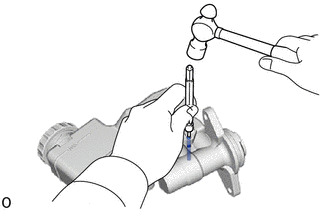
1. REMOVE BRAKE MASTER CYLINDER RING PIN
(a) Secure the brake master cylinder sub-assembly in a vise.
NOTICE:
Place aluminum plates on the vise to prevent damage to the brake master cylinder sub-assembly.
| (b) Using a 5 mm pin punch and a hammer, tap out the brake master cylinder ring pin from the brake master cylinder sub-assembly. NOTICE: Do not drop the brake master cylinder reservoir assembly. |
|
2. REMOVE BRAKE MASTER CYLINDER RESERVOIR ASSEMBLY
(a) Remove the brake master cylinder reservoir assembly from the brake master cylinder body.
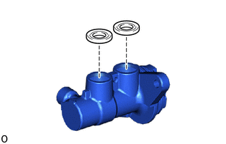
3. REMOVE MASTER CYLINDER RESERVOIR GROMMET
| (a) Remove the 2 master cylinder reservoir grommets from the brake master cylinder body. |
|
(b) Remove the brake master cylinder body from the vise.
4. REMOVE BRAKE MASTER CYLINDER RESERVOIR FILLER CAP ASSEMBLY
(a) Remove the brake master cylinder reservoir filler cap assembly from the brake master cylinder reservoir assembly.
5. REMOVE BRAKE MASTER CYLINDER RESERVOIR STRAINER
(a) Remove the brake master cylinder reservoir strainer from the brake master cylinder reservoir assembly.
 Removal
REMOVAL CAUTION / NOTICE / HINT The necessary procedures (adjustment, calibration, initialization, or registration) that must be performed after parts are removed, installed, or replaced during the brake master cylinder sub-assembly removal/installation are shown below...
 Reassembly
REASSEMBLY PROCEDURE 1. INSTALL BRAKE MASTER CYLINDER RESERVOIR STRAINER (a) Install the brake master cylinder reservoir strainer to the brake master cylinder reservoir assembly...
Other information:
Toyota Yaris XP210 (2020-2026) Reapir and Service Manual: Components
C..
Toyota Yaris XP210 (2020-2026) Reapir and Service Manual: Front Recognition Camera Optical Axis Misalignment Malfunction (C1AA800)
DESCRIPTION The forward recognition camera monitors its optical axis status. If it determines that the optical axis alignment has become misaligned, it will store DTC C1AA800. DTC No. Detection Item DTC Detection Condition Trouble Area C1AA800 Front Recognition Camera Optical Axis Misalignment Malfunction When the forward recognition camera detects an optical axis misalignment when the vehicle is being driven at a speed of 5 km/h (4 mph) or more, after 2 seconds have elapsed since the ignition switch was turned ON...
Categories
- Manuals Home
- Toyota Yaris Owners Manual
- Toyota Yaris Service Manual
- G16e-gts (engine Mechanical)
- Fuse Panel Description
- Diagnostic Trouble Code Chart
- New on site
- Most important about car
Supplemental Restraint System (SRS) Precautions
The front and side supplemental restraint systems (SRS) include different types of air bags. Please verify the different types of air bags which are equipped on your vehicle by locating the “SRS AIRBAG” location indicators. These indicators are visible in the area where the air bags are installed.
The air bags are installed in the following locations:
The steering wheel hub (driver air bag) The front passenger dashboard (front passenger air bag) The outboard sides of the front seatbacks (side air bags) The front and rear window pillars, and the roof edge along both sides (curtain air bags)