Toyota Yaris: Rear Coil Spring / Installation
INSTALLATION
CAUTION / NOTICE / HINT
HINT:
- Use the same procedure for the RH side and LH side.
- The following procedure is for the LH side.
PROCEDURE
1. INSTALL REAR UPPER COIL SPRING INSULATOR
(a) Install the rear upper coil spring insulator to the vehicle body.
2. INSTALL REAR LOWER COIL SPRING INSULATOR
(a) Install the rear lower coil spring insulator to the rear No. 2 suspension arm assembly.
3. INSTALL REAR COIL SPRING
(a) Set the rear coil spring to the rear No. 2 suspension arm assembly.
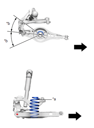
| *a | Identification Mark |
| *b | 30° or less |
 | Inner Side of the Vehicle |
NOTICE:
- Set the rear coil spring so that its lower end is within the range shown in the illustration.
- Set the rear coil spring so that the identification mark is positioned as shown in the illustration.
(b) Using a jack and wooden block, slowly jack up the rear No. 2 suspension arm assembly and then install the rear No. 2 suspension arm assembly to the rear axle carrier sub-assembly with the bolt and nut.
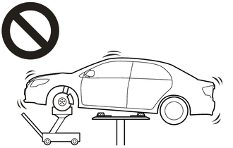
- Do not raise the jack up too high.
- The vehicle could fall, resulting in a serious accident.
NOTICE:
- Tighten the bolt with the nut secured.
- When jacking up the rear No. 2 suspension arm assembly, be sure to jack it up slowly.
- Make sure to perform this operation with the vehicle kept as low as possible.
- Insert the bolt with the threaded end facing the front of the vehicle.
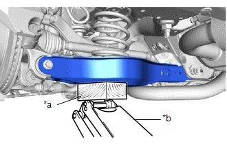
| *a | Wooden Block |
| *b | Jack |
4. STABILIZE SUSPENSION
Click here

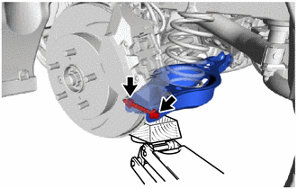
5. FULLY TIGHTEN REAR NO. 2 SUSPENSION ARM ASSEMBLY
| (a) Install the rear No. 2 suspension arm assembly (rear axle carrier sub-assembly side) with the bolt. Torque: 73 N·m {744 kgf·cm, 54 ft·lbf} NOTICE: Tighten the bolt with the nut secured. |
|
6. INSTALL REAR STABILIZER LINK ASSEMBLY
Click here

7. INSTALL REAR WHEEL
Click here

8. FULLY TIGHTEN REAR NO. 2 SUSPENSION ARM ASSEMBLY
(a) Install the rear No. 2 suspension arm assembly (rear suspension member sub-assembly side) with the nut.
Click here

9. INSPECT AND ADJUST REAR WHEEL ALIGNMENT
Click here

 Removal
REMOVAL CAUTION / NOTICE / HINT The necessary procedures (adjustment, calibration, initialization, or registration) that must be performed after parts are removed and installed, or replaced during rear coil spring removal/installation are shown below...

Other information:
Toyota Yaris XP210 (2020-2026) Reapir and Service Manual: Inspection
INSPECTION PROCEDURE 1. INSPECT CYLINDER BLOCK FOR WARPAGE (a) Using a precision straightedge and feeler gauge, check the surface which contacts the cylinder head gasket for warpage. Maximum Warpage: 0.05 mm (0.00197 in.) HINT: If the warpage is more than the maximum, replace the cylinder block sub-assembly...
Toyota Yaris XP210 (2020-2026) Reapir and Service Manual: Removal
REMOVAL CAUTION / NOTICE / HINT The necessary procedures (adjustment, calibration, initialization or registration) that must be performed after parts are removed and installed, or replaced during fuel pump removal/installation are shown below. Necessary Procedures After Parts Removed/Installed/Replaced Replaced Part or Performed Procedure Necessary Procedure Effect/Inoperative Function when Necessary Procedure not Performed Link Replacement of fuel pump Inspection after repair Poor idle, etc...
Categories
- Manuals Home
- Toyota Yaris Owners Manual
- Toyota Yaris Service Manual
- Opening and Closing the Liftgate/Trunk Lid
- Battery Monitor Module General Electrical Failure (P058A01)
- Maintenance
- New on site
- Most important about car
Refueling
Before refueling, close all the doors, windows, and the liftgate/trunk lid, and switch the ignition OFF.
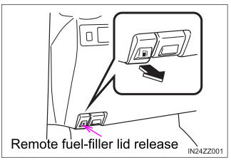
To open the fuel-filler lid, pull the remote fuel-filler lid release.