Toyota Yaris: G16e-gts (emission Control) / Vacuum Regulating Valve
Components
COMPONENTS
ILLUSTRATION
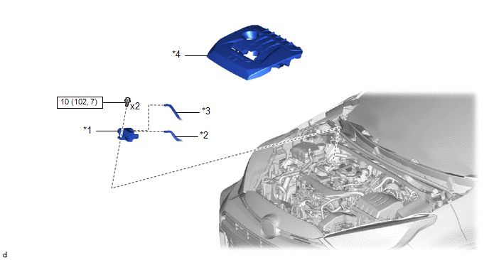
| *1 | VACUUM REGULATING VALVE ASSEMBLY | *2 | NO. 2 VACUUM TRANSMITTING HOSE |
| *3 | NO. 1 VACUUM TRANSMITTING HOSE | *4 | NO. 1 ENGINE COVER SUB-ASSEMBLY |
 | N*m (kgf*cm, ft.*lbf): Specified torque | - | - |
Removal
REMOVAL
PROCEDURE
1. REMOVE NO. 1 ENGINE COVER SUB-ASSEMBLY
Click here

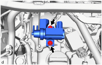
2. REMOVE VACUUM REGULATING VALVE ASSEMBLY
| (a) Disconnect the No. 1 vacuum transmitting hose from the vacuum regulating valve assembly. |
|
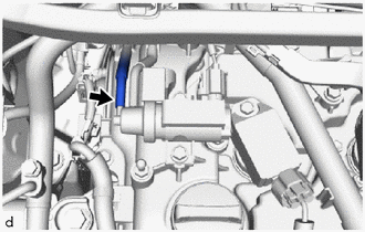
| (b) Disconnect the No. 2 vacuum transmitting hose from the vacuum regulating valve assembly. |
|
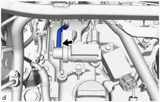
| (c) Disconnect the vacuum regulating valve assembly connector. |
|
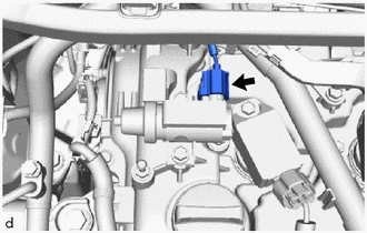
| (d) Remove the 2 bolts and vacuum regulating valve assembly from the cylinder head cover sub-assembly. |
|
Inspection
INSPECTION
PROCEDURE
1. INSPECT VACUUM REGULATING VALVE ASSEMBLY
(a) Measure the resistance according to the value(s) in the table below.
Standard Resistance:
| Tester Connection | Condition | Specified Condition |
|---|---|---|
| 1 - 2 | 20°C (68°F) | 11.1 to 12.5 Ω |
If the result is not as specified, replace the vacuum regulating valve assembly.
(b) Check the operation of the vacuum regulating valve assembly.
| (1) Using a vacuum pump, apply a vacuum of 67 kPa (503 mmHg, 19.8 in. Hg) to the port (F) and check that the vacuum regulating valve assembly operates normally. |
|
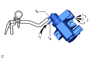
(2) Check that air flows from the filter when air is blown into the port (E).
HINT:
When air is blown into the port (E), the vacuum of the port (F) decreases.
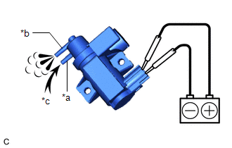
| (3) Apply auxiliary battery voltage between the terminals, and check that air flows from the port (F) when air is blown into the port (E). |
|
Installation
INSTALLATION
PROCEDURE
1. INSTALL VACUUM REGULATING VALVE ASSEMBLY
(a) Install the vacuum regulating valve assembly to the cylinder head cover sub-assembly with the 2 bolts.
Torque:
10 N·m {102 kgf·cm, 7 ft·lbf}
(b) Connect the vacuum regulating valve assembly connector.
(c) Connect the No. 2 vacuum transmitting hose to the vacuum regulating valve assembly.
(d) Connect the No. 1 vacuum transmitting hose to the vacuum regulating valve assembly.
2. INSTALL NO. 1 ENGINE COVER SUB-ASSEMBLY
Click here

 Purge Valve
ComponentsCOMPONENTS ILLUSTRATION
*1 FUEL VAPOR FEED HOSE ASSEMBLY *2 NO. 1 FUEL VAPOR FEED HOSE *3 PURGE VALVE (PURGE VSV) *4 NO...

Other information:
Toyota Yaris XP210 (2020-2026) Reapir and Service Manual: Precaution
PRECAUTION CAUTION REGARDING INTERFERENCE WITH ELECTRONIC DEVICES CAUTION: As weak radio waves are emitted from the electrical key transmitter sub-assembly, if a pacemaker is being used, be sure to read the pacemaker instruction manual and the following...
Toyota Yaris XP210 (2020-2026) Reapir and Service Manual: Components
C..
Categories
- Manuals Home
- Toyota Yaris Owners Manual
- Toyota Yaris Service Manual
- To Set Speed
- Fuel Gauge
- Power Integration No.1 System Missing Message (B235287,B235587,B235787-B235987)
- New on site
- Most important about car
Fuel Gauge
The fuel gauge shows approximately how much fuel is remaining in the tank when the ignition is switched ON. We recommend keeping the tank over 1/4 full.
