Toyota Yaris: G16e-gts (emission Control) / Purge Valve
Components
COMPONENTS
ILLUSTRATION
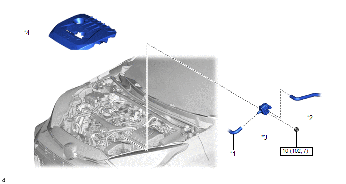
| *1 | FUEL VAPOR FEED HOSE ASSEMBLY | *2 | NO. 1 FUEL VAPOR FEED HOSE |
| *3 | PURGE VALVE (PURGE VSV) | *4 | NO. 1 ENGINE COVER SUB-ASSEMBLY |
 | N*m (kgf*cm, ft.*lbf): Specified torque | - | - |
Removal
REMOVAL
PROCEDURE
1. REMOVE NO. 1 ENGINE COVER SUB-ASSEMBLY
Click here

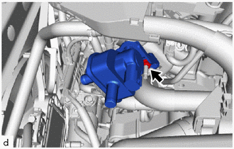
2. REMOVE PURGE VALVE (PURGE VSV)
| (a) Disconnect the purge valve (purge VSV) connector. |
|
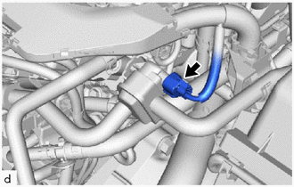
| (b) Disconnect the fuel vapor feed hose assembly from the purge valve (purge VSV). |
|
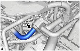
| (c) Disconnect the No. 1 fuel vapor feed hose from the purge valve (purge VSV). |
|
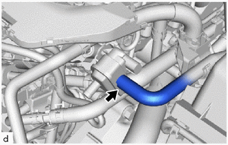
| (d) Remove the nut and purge valve (purge VSV) from the intake manifold. |
|
Inspection
INSPECTION
PROCEDURE
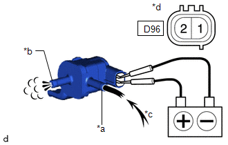
1. INSPECT PURGE VALVE (PURGE VSV)
(a) Measure the resistance according to the value(s) in the table below.
Standard Resistance:
| Tester Connection | Condition | Specified Condition |
|---|---|---|
| D96-1 - D96-2 | 20°C (68°F) | 23 to 26 Ω |
If the result is not as specified, replace the purge valve (purge VSV).
| (b) Apply auxiliary battery voltage between the terminals of the purge valve (purge VSV) and check that the following occurs when blowing air into the port (E). OK:
If the result is not as specified, replace the purge valve (purge VSV). |
|
Installation
INSTALLATION
PROCEDURE
1. INSTALL PURGE VALVE (PURGE VSV)
(a) Install the purge valve (purge VSV) to the intake manifold with the nut.
Torque:
10 N·m {102 kgf·cm, 7 ft·lbf}
(b) Connect the No. 1 fuel vapor feed hose to the purge valve (purge VSV).
(c) Connect the fuel vapor feed hose assembly to the purge valve (purge VSV).
(d) Connect the purge valve (purge VSV) connector.
2. INSTALL NO. 1 ENGINE COVER SUB-ASSEMBLY
Click here

 Pcv Valve
ComponentsCOMPONENTS ILLUSTRATION
*1 PCV VALVE (VENTILATION VALVE SUB-ASSEMBLY) - - On-vehicle InspectionON-VEHICLE INSPECTION PROCEDURE 1...
 Vacuum Regulating Valve
ComponentsCOMPONENTS ILLUSTRATION
*1 VACUUM REGULATING VALVE ASSEMBLY *2 NO. 2 VACUUM TRANSMITTING HOSE *3 NO. 1 VACUUM TRANSMITTING HOSE *4 NO...
Other information:
Toyota Yaris XP210 (2020-2026) Reapir and Service Manual: Removal
REMOVAL CAUTION / NOTICE / HINT HINT: When the cable is disconnected/reconnected to the auxiliary battery terminal, systems temporarily stop operating. However, each system has a function that completes learning the first time the system is used. Learning completes when vehicle is driven Effect/Inoperative Function When Necessary Procedures are not Performed Necessary Procedures Link Lane tracing assist system Drive the vehicle straight ahead at 35 km/h (22 mph) or more for 5 second or more...
Toyota Yaris XP210 (2020-2026) Reapir and Service Manual: Precaution
PRECAUTION CAUTION REGARDING INTERFERENCE WITH ELECTRONIC DEVICES CAUTION: As weak radio waves are emitted from the electrical key transmitter sub-assembly, if a pacemaker is being used, be sure to read the pacemaker instruction manual and the following...
Categories
- Manuals Home
- Toyota Yaris Owners Manual
- Toyota Yaris Service Manual
- Power Integration No.1 System Missing Message (B235287,B235587,B235787-B235987)
- Fuse Panel Description
- Opening and Closing the Liftgate/Trunk Lid
- New on site
- Most important about car
Fuel-Filler Lid and Cap
WARNING
When removing the fuel-filler cap, loosen the cap slightly and wait for any hissing to stop, then remove it
Fuel spray is dangerous. Fuel can burn skin and eyes and cause illness if ingested. Fuel spray is released when there is pressure in the fuel tank and the fuel-filler cap is removed too quickly.