Toyota Yaris: Theft Deterrent System / Check For Intermittent Problems
CHECK FOR INTERMITTENT PROBLEMS
NOTICE:
- If the vehicle or vehicle controls are operated (for example, during initial inspection when the vehicle is brought in for repair) before vehicle control history (RoB) has been read out and saved, the vehicle control history (RoB) information could be lost.
- The function "Read vehicle control history (RoB)" uses the current system time setting inside the GTS and the time counter inside the controlling ECU to calculate the timings shown in the vehicle control history (RoB). For this reason, before reading out the vehicle control history (RoB), first make sure that the GTS system clock is accurately set to the current time.
- The time counter in the control ECU may deviate by up to +/- 10% due to the characteristics of the time counter.
- The time counter in the control ECU is reset approximately 34 days before the "Current" value due to the characteristics of the time counter. Therefore, the time information stored before the 34th day may not be accurately displayed.
Vehicle Control History (RoB)
HINT:
Vehicle control history (RoB): The main body ECU (multiplex network body ECU) records the theft deterrent system vehicle control history (RoB), which can be read out using the GTS.
(a) Enter the following menus: Body Electrical / Main Body / Utility / Vehicle Control History (RoB).
Body Electrical > Main Body > Utility| Tester Display |
|---|
| Vehicle Control History (RoB) |
| RoB Code | RoB Item | Item description | Note |
|---|---|---|---|
| X2304 | Security Alarm Operation | Security alarm is to store a factor when activated. | The factor that triggered the security alarm is stored. |
| X2305 | Intrusion Operation | The set value is stored when the intrusion sensor is turned off or when the sensitivity setting is changed. | When the setting of the intrusion sensor is changed, the setting value is stored. |
(b) Following the instructions on the screen, save the vehicle control history (RoB).
Security Alarm Operation| Vehicle Control History (RoB) List |
|---|
| Battery Desorption |
| Hood Open |
| Luggage / Back Door Open |
| FR Door Open |
| FR Door Unlock |
| IG |
| Intrusion Sensor |
| Glass Sensor |
| Inclination Sensor |
| FL Door Open |
| RR Door Open |
| RL Door Open |
| FL Door Unlock |
| RR Door Unlock |
| RL Door Unlock |
| Back Door Unlock |
| Panic Alarm |
| Detect Intrusion Sensor Window Open |
| Vehicle Control History (RoB) List |
|---|
| Intrusion Sensor OFF |
| Intrusion Sensor OFF Cancel |
| Intrusion Sensor Sound Setting |
| Intrusion Sensor Window Open Setting |
| Intrusion Sensor Sensitivity Level Down |
| Intrusion Sensor Sound Detection Cancel |
HINT:
Some items are not displayed depending on the vehicle.
Symptom Simulation
Click here

 System Description
SYSTEM DESCRIPTION OUTLINE OF THEFT DETERRENT SYSTEM
The theft deterrent system can be set by locking the doors using any of the following operations:
Entry lock operation
Wireless lock operation
Key linked lock operation
By opening and closing the doors
In the armed state, the alarm function will be activated if one of the following conditions is met:
Any of the doors are unlocked...
 Customize Parameters
CUSTOMIZE PARAMETERS INSTALL CUSTOMIZE THEFT DETERRENT SYSTEM HINT: The following items can be customized. NOTICE:
When the customer requests a change in a function, first make sure that the function can be customized...
Other information:
Toyota Yaris XP210 (2020-2026) Owner's Manual: Low Speed Pre-Collision System
The Low Speed Pre-Collision System is designed to reduce damage in the event of a collision by operating the brake control (Low Speed Pre-Collision System brake) when the system’s laser sensor detects a vehicle ahead and determines that a collision with a vehicle ahead is unavoidable...
Toyota Yaris XP210 (2020-2026) Reapir and Service Manual: Rocker Panel Moulding
ComponentsCOMPONENTS ILLUSTRATION *1 ROCKER PANEL MOULDING - - RemovalREMOVAL CAUTION / NOTICE / HINT HINT: Use the same procedure for the RH side and LH side. The following procedure is for the LH side. PROCEDURE 1. REMOVE REAR WHEEL HOUSE FRONT PLATE Click here 2...
Categories
- Manuals Home
- Toyota Yaris Owners Manual
- Toyota Yaris Service Manual
- Opening and Closing the Liftgate/Trunk Lid
- How to connect USB port/Auxiliary jack
- Engine Start Function When Key Battery is Dead
- New on site
- Most important about car
Keys

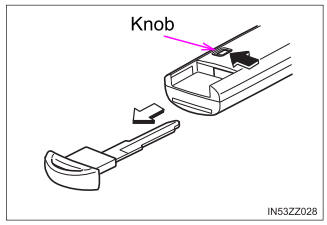
To use the auxiliary key, press the knob and pull out the auxiliary key from the smart key.

