Toyota Yaris: Exterior Panels / Trim / Rocker Panel Moulding
Components
COMPONENTS
ILLUSTRATION
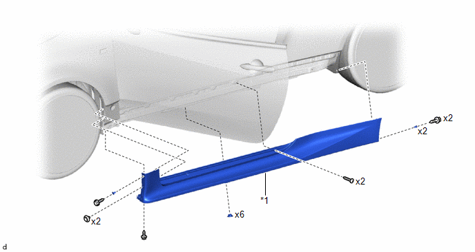
| *1 | ROCKER PANEL MOULDING | - | - |
Removal
REMOVAL
CAUTION / NOTICE / HINT
HINT:
- Use the same procedure for the RH side and LH side.
- The following procedure is for the LH side.
PROCEDURE
1. REMOVE REAR WHEEL HOUSE FRONT PLATE
Click here
.gif)
2. REMOVE ROCKER PANEL MOULDING
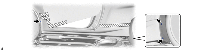
(a) Apply protective tape around the rocker panel moulding and front door panel as shown in the illustration.

.png) | Protective Tape | - | - |
(b) Remove the 6 clips.

(c) Remove the 2 clips and 6 screws.

(d) Remove the 3 grommets.
(e) Disengage the clips to remove the rocker panel moulding as shown in the illustration.
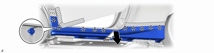
.png) | Remove in this Direction | - | - |
Installation
INSTALLATION
CAUTION / NOTICE / HINT
HINT:
- Use the same procedure for the RH side and LH side.
- The following procedure is for the LH side.
PROCEDURE
1. INSTALL ROCKER PANEL MOULDING
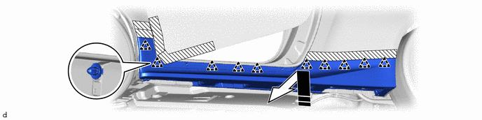
(a) Engage the clips to install the rocker panel moulding as shown in the illustration.
.png) | Protective Tape |
.png) | Install in this Direction |
(b) Install the 3 grommets.
(c) Install the 2 clips and 6 screws.
(d) Install the 6 clips.
(e) Remove the protective tape.
2. INSTALL REAR WHEEL HOUSE FRONT PLATE
Click here
.gif)
 Rear Wheel House Plate
ComponentsCOMPONENTS ILLUSTRATION
*1 REAR WHEEL HOUSE FRONT PLATE - - RemovalREMOVAL CAUTION / NOTICE / HINT HINT:
Use the same procedure for the RH and LH sides...

Other information:
Toyota Yaris XP210 (2020-2026) Reapir and Service Manual: Dtc Check / Clear
DTC CHECK / CLEAR NOTICE: When DTC is output, be sure to confirm and record. DTCs may have been stored due to problems unrelated to the steering lock function. Be sure to confirm and record any DTCs output for other systems. When using the GTS with the ignition switch off, connect the GTS to the DLC3 and turn a courtesy light switch on and off at intervals of 1...
Toyota Yaris XP210 (2020-2026) Reapir and Service Manual: Diagnostic Trouble Code Chart
D..
Categories
- Manuals Home
- Toyota Yaris Owners Manual
- Toyota Yaris Service Manual
- Engine Start Function When Key Battery is Dead
- Headlights
- Diagnostic Trouble Code Chart
- New on site
- Most important about car
Fuel Gauge
The fuel gauge shows approximately how much fuel is remaining in the tank when the ignition is switched ON. We recommend keeping the tank over 1/4 full.
