Toyota Yaris: Charging System / Terminals Of Ecm
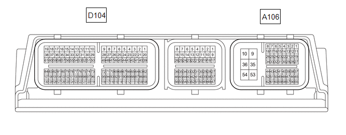
TERMINALS OF ECM
CHECK ECM
HINT:
The standard normal voltage between each pair of ECM terminals is shown in the table below. The appropriate conditions for checking each pair of terminals are also indicated. The result of checks should be compared with the standard normal voltage for that pair of terminals, displayed in the Specified Condition column. The illustration above can be used as a reference to identify the ECM terminal locations.
| Terminal No. (Symbol) | Terminal Description | Condition | Specified Condition |
|---|---|---|---|
| A106-1 (BATT) - A106-10 (E1) | Auxiliary battery (for measuring auxiliary battery voltage and for ECM memory) | Always | 11 to 14 V |
| A106-10 (E1) - Body ground | Ground | Always | Below 1 Ω |
| D104-62 (LIN) - Body ground | LIN communication line | Ignition switch off (while LIN communication stopped) | 10 kΩ or higher |
 Problem Symptoms Table
PROBLEM SYMPTOMS TABLE HINT:
Use the table below to help determine the cause of problem symptoms. If multiple suspected areas are listed, the potential causes of the symptoms are listed in order of probability in the "Suspected Area" column of the table...
 Diagnosis System
DIAGNOSIS SYSTEM DLC3 (Data Link Connector 3) (a) Check the DLC3. Click here
HINT: If the voltage is below 11 V, replace or recharge the auxiliary battery...
Other information:
Toyota Yaris XP210 (2020-2026) Reapir and Service Manual: Disassembly
DISASSEMBLY PROCEDURE 1. REMOVE MILLIMETER WAVE RADAR SENSOR ASSEMBLY (w/ Pre-collision System) Click here 2. REMOVE NO. 3 ENGINE ROOM WIRE (w/ Pre-collision System) (a) Disengage the clamps to remove the No. 3 engine room wire. 3. REMOVE FOG LIGHT ASSEMBLY LH Click here 4...
Toyota Yaris XP210 (2020-2026) Reapir and Service Manual: Calibration
CALIBRATION NOTICE: When the AWD ECU assembly is replaced, before removing the AWD ECU assembly, it is necessary to perform ECU Data Save to save the original AWD ECU assembly information. When the AWD ECU assembly is replaced, it is necessary to perform the following in order: ECU Data Initialization and ECU Data Write...
Categories
- Manuals Home
- Toyota Yaris Owners Manual
- Toyota Yaris Service Manual
- Adjustment
- Auto Lock/Unlock Function
- Brake System Control Module "A" System Voltage System Voltage Low (C137BA2)
- New on site
- Most important about car
Keys

To use the auxiliary key, press the knob and pull out the auxiliary key from the smart key.
