Toyota Yaris: Smart Key System (for Start Function) / Engine Immobiliser System Circuit Short to Battery (B279A12)
DESCRIPTION
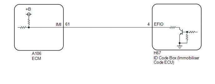
If the communication line (IMI - EFIO) between the ECM and ID code box (immobiliser code ECU) is stuck high, the ECM will store this DTC.
| DTC No. | Detection Item | DTC Detection Condition | Trouble Area | Note |
|---|---|---|---|---|
| B279A12 | Engine Immobiliser System Circuit Short to Battery | The communication line (IMI - EFIO) between the ECM and ID code box (immobiliser code ECU) is stuck high. (1 trip detection logic*) |
| DTC output confirmation operation:
|
- *: Only output while a malfunction is present.
| Vehicle Condition when Malfunction Detected | Fail-safe Operation when Malfunction Detected |
|---|---|
| Engine cannot be started | Engine cannot be started |
| DTC No. | Data List and Active Test |
|---|---|
| B279A12 | - |
WIRING DIAGRAM
CAUTION / NOTICE / HINT
NOTICE:
- When using the GTS with the ignition switch off, connect the GTS to the DLC3 and turn a courtesy light switch on and off at intervals of 1.5 seconds or less until communication between the GTS and the vehicle begins. Then select the vehicle type under manual mode and enter the following menus: Body Electrical / Smart Key. While using the GTS, periodically turn a courtesy light switch on and off at intervals of 1.5 seconds or less to maintain communication between the GTS and the vehicle.
-
The smart key system (for Start Function) uses the LIN communication system and CAN communication system. Inspect the communication function by following How to Proceed with Troubleshooting. Troubleshoot the smart key system (for Start Function) after confirming that the communication systems are functioning properly.
Click here

-
Before replacing the ECM or ID code box (immobiliser code ECU), refer to the Registration.
Click here

- After performing repairs, confirm that no DTCs are output by performing "DTC Output Confirmation Operation".
HINT:
When DTC B279A12 and the certification ECU (smart key ECU assembly) DTC are output simultaneously, first perform troubleshooting for the certification ECU (smart key ECU assembly) DTC.
PROCEDURE
| 1. | CHECK CONNECTION OF CONNECTOR |
(a) Turn the ignition switch off.
(b) Check that the connectors are properly connected to the ECM and ID code box (immobiliser code ECU).
OK:
Connectors are properly connected.
| NG |
 | CONNECT CONNECTORS PROPERLY |
|

| 2. | CHECK ID CODE BOX (IMMOBILISER CODE ECU) (TERMINAL EFIO) |
(a) Using an oscilloscope, check the waveform.
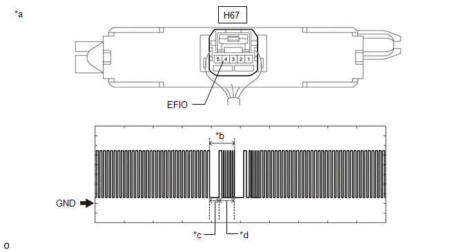
| *a | Component with harness connected (ID Code Box (Immobiliser Code ECU)) | *b | Waveform |
| *c | Approximately 160 ms. | *d | Approximately 270 ms. |
OK:
| Tester Connection | Condition | Tool Setting | Specified Condition |
|---|---|---|---|
| H67-4 (EFIO) - Body ground | Within 3 seconds of engine start or within 3 seconds of ignition switch turned to ON after cable disconnected and reconnected to auxiliary battery | 2 V/DIV., 500 ms./DIV. | Pulse generation (See waveform) |
| Result | Proceed to |
|---|---|
| 11 to 14 V | A |
| Below 1 V | B |
| Normal wavform | C |
| A |
 | REPLACE ID CODE BOX (IMMOBILISER CODE ECU) |
| C |
 | REPLACE ECM |
|

| 3. | CHECK HARNESS AND CONNECTOR (ID CODE BOX (IMMOBILISER CODE ECU) - ECM) |
(a) Disconnect the A106 ECM connector.
(b) Disconnect the H67 ID code box (immobiliser code ECU) connector.
(c) Measure the resistance according to the value(s) in the table below.
Standard Resistance:
| Tester Connection | Condition | Specified Condition |
|---|---|---|
| A106-61 (IMI) - H67-4 (EFIO) | Always | Below 1 Ω |
| OK |
 | REPLACE ECM |
| NG |
 | REPAIR OR REPLACE HARNESS OR CONNECTOR |
 Engine Immobiliser System Signal (Some Circuit Quantity, Reported via Serial Data) Invalid (B279986)
DESCRIPTION If there is a communication malfunction between the ECM and ID code box (immobiliser code ECU), or when the communication ID codes do not match, the ECM stores this DTC...
 Engine Immobiliser System Incorrect Assembly (B279C95)
DESCRIPTION If an ECM that is incompatible with the immobiliser function is installed, the ECM will store this DTC. DTC No. Detection Item DTC Detection Condition Trouble Area Note B279C95 Engine Immobiliser System Incorrect Assembly An ECM that is incompatible with the immobiliser function is installed...
Other information:
Toyota Yaris XP210 (2020-2026) Reapir and Service Manual: Inspection Mode Procedure
INSPECTION MODE PROCEDURE INSPECTION MODE (a) for Gasoline Model, Diesel Model, LPG Model: The following table shows the types of inspection mode that are available, their purpose and the control that occurs in mode. Utility Items Main Purpose Control Inspection Mode For performing tests using a speedometer tester, two-wheel chassis dynamometer, four-wheel chassis dynamometer, etc...
Toyota Yaris XP210 (2020-2026) Reapir and Service Manual: HO2S Heater Control Circuit Bank 1 Sensor 2 Circuit Short to Battery (P003612,P003613,P102A9E)
DESCRIPTION The air fuel ratio sensor (sensor 2) generates current that corresponds to the actual air fuel ratio. This sensor current is used to provide the ECM with feedback so that it can control the air fuel ratio. The ECM determines the deviation from the stoichiometric air fuel ratio level, and regulates the fuel injection duration...
Categories
- Manuals Home
- Toyota Yaris Owners Manual
- Toyota Yaris Service Manual
- Power Integration No.1 System Missing Message (B235287,B235587,B235787-B235987)
- Immobilizer System
- Battery Monitor Module General Electrical Failure (P058A01)
- New on site
- Most important about car
Turning the Engine Off
Stop the vehicle completely. Manual transaxle: Shift into neutral and set the parking brake.Automatic transaxle: Shift the selector lever to the P position and set the parking brake.
Press the push button start to turn off the engine. The ignition position is off.