Toyota Yaris: Rear Differential Carrier Assembly / Removal
REMOVAL
CAUTION / NOTICE / HINT
The necessary procedures (adjustment, calibration, initialization, or registration) that must be performed after parts are removed and installed, or replaced during the rear differential carrier assembly removal/installation are shown below.
Necessary Procedure After Parts Removed/Installed/Replaced| Replaced Part or Performed Procedure | Necessary Procedure | Effect/Inoperative Function when Necessary Procedure not Performed | Link |
|---|---|---|---|
| Replacement of 4WD linear solenoid (transmission coupling assembly) | ECU data write | Active torque split AWD system |
|
| Gas leaks from exhaust system | Inspection after repair |
|
|
| Rear wheel alignment adjustment | Calibration |
|
|


CAUTION:
-
To prevent burns, do not touch the engine, exhaust pipe or other high temperature components while the engine is hot.
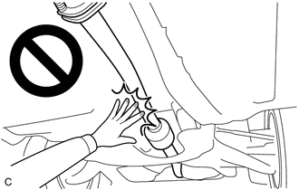
-
The rear differential carrier assembly is very heavy. Be sure to follow the procedure described in the repair manual, or the engine lifter may suddenly drop or the rear differential carrier assembly may fall off the engine lifter.
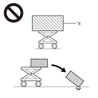
*a
An Object Exceeding Weight Limit of Engine Lifter
PROCEDURE
1. DRAIN DIFFERENTIAL OIL
Click here

2. REMOVE PROPELLER WITH CENTER BEARING SHAFT ASSEMBLY
Click here

3. REMOVE REAR DRIVE SHAFT ASSEMBLY
Click here

4. REMOVE REAR STABILIZER BAR
Click here

5. LOOSEN REAR NO. 1 DIFFERENTIAL SUPPORT
| (a) Loosen the 2 bolts. |
|
6. REMOVE REAR DIFFERENTIAL CARRIER ASSEMBLY
NOTICE:
- Do not damage the contact surface when removing the rear differential carrier assembly.
- The remaining oil may leak out when removing the rear differential carrier assembly.
- Securely support the rear differential carrier assembly while performing this step to avoid excessively tilting or dropping the rear differential carrier assembly.
- Remove the bolts and nuts with the rear differential carrier assembly secured.
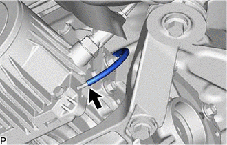
| (a) Disconnect the vacuum hose from the electro magnetic control coupling sub-assembly. |
|
| (b) Support the rear differential carrier assembly with an engine lifter using 2 attachments or equivalent tools as shown in the illustration. |
|
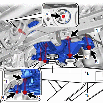
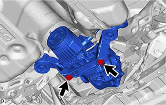
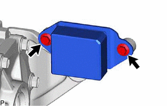
(c) Remove the bolt (A) from the rear differential support.
(d) Remove the 2 bolts (B), and 2 rear lower differential mount stoppers from the rear No. 1 differential support.
(e) Remove the 2 bolts (C), 2 nuts from the rear No. 1 differential support.
HINT:
The nuts have tabs to prevent them from rotating.
| (f) Disconnect the connector and disengage the clamp (A). |
|
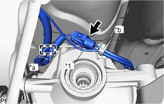
(g) Separate the vacuum hose from the clamp (B).
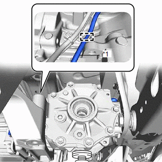
| (h) Slightly lower the rear differential carrier assembly, remove the vacuum hose from the clamp. NOTICE: Do not damage the vacuum hose and electro magnetic control coupling wire harness. HINT: Lower the engine lifter to the extent that the vacuum hose can still be removed. |
|
(i) Lower the rear differential carrier assembly slowly to remove the rear differential carrier assembly.
NOTICE:
- Do not damage the vacuum hose and electro magnetic control coupling wire harness.
- Move the engine lifter forward and backward as necessary to prevent the rear differential carrier assembly from contacting the rear suspension member sub-assembly.
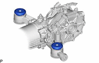
7. REMOVE REAR UPPER DIFFERENTIAL MOUNT STOPPER
| (a) Remove the 2 rear upper differential mount stoppers from the rear No. 1 differential support. |
|
8. REMOVE REAR DIFFERENTIAL DYNAMIC DAMPER
| (a) Remove the 2 bolts and rear differential dynamic damper from the rear differential support. |
|
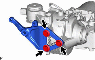
9. REMOVE REAR DIFFERENTIAL SUPPORT
| (a) Remove the 3 bolts and rear differential support from the rear differential carrier assembly. |
|
 Components
COMPONENTS ILLUSTRATION
*1 REAR DIFFERENTIAL DRAIN PLUG *2 REAR DIFFERENTIAL FILLER PLUG *3 GASKET - -
Tightening torque for "Major areas involving basic vehicle performance such as moving/turning/stopping" : N*m (kgf*cm, ft...
 Disassembly
DISASSEMBLY CAUTION / NOTICE / HINT NOTICE:
Before installation, thoroughly clean and dry each part and then apply Toyota Genuine Differential gear oil LX SAE 75W-85 GL-5 or equivalent to them...
Other information:
Toyota Yaris XP210 (2020-2026) Reapir and Service Manual: Installation
INSTALLATION PROCEDURE 1. INSTALL POWER WINDOW REGULATOR MOTOR ASSEMBLY (a) Apply MP grease to the sliding and rotating areas of the power window regulator motor assembly. (b) Install the power window regulator motor assembly with the 3 bolts. Torque: 5...
Toyota Yaris XP210 (2020-2026) Reapir and Service Manual: Installation
INSTALLATION PROCEDURE 1. INSTALL WINDSHIELD WIPER SWITCH ASSEMBLY (a) Turn the steering wheel assembly to the right. (b) Engage the claw to install the windshield wiper switch assembly as shown in the illustration. Install in this Direction 2...
Categories
- Manuals Home
- Toyota Yaris Owners Manual
- Toyota Yaris Service Manual
- Battery Monitor Module General Electrical Failure (P058A01)
- Maintenance
- Headlights
- New on site
- Most important about car
Refueling
Before refueling, close all the doors, windows, and the liftgate/trunk lid, and switch the ignition OFF.
To open the fuel-filler lid, pull the remote fuel-filler lid release.
