Toyota Yaris: Roof Headlining / Reassembly
REASSEMBLY
PROCEDURE
1. INSTALL NO. 2 ANTENNA CORD SUB-ASSEMBLY
Click here

2. INSTALL NO. 1 ROOF WIRE
(a) Apply butyl tape onto the roof headlining so that it does not protrude from the markings.
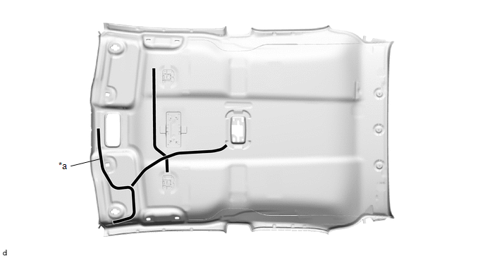
| *a | Butyl Tape | - | - |
HINT:
Apply the butyl tape securely, making sure that it is not out of position or peeling off.
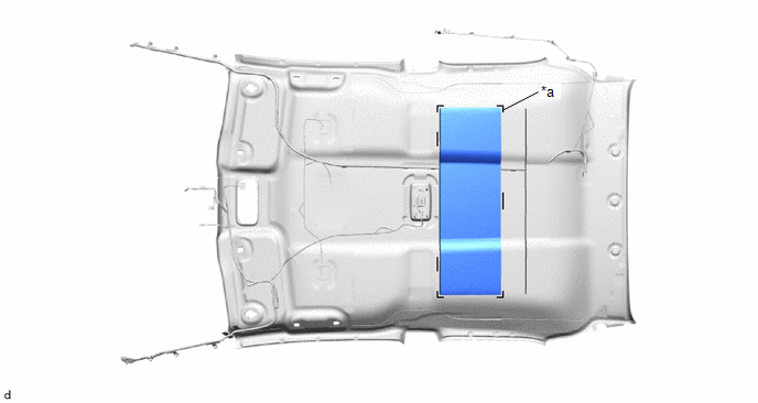
(b) Line up the No. 1 roof wire positioning tape and the roof headlining markings as shown in the illustration.
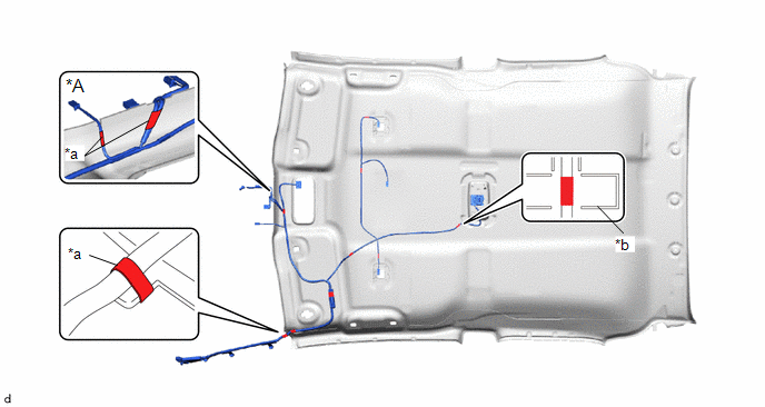
| *A | w/ Pre-collision System | - | - |
| *a | Positioning Tape | *b | Marking |
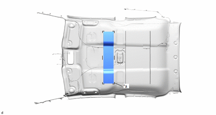
(c) Install the No. 1 roof wire with new pieces of each adhesive tape as shown in the illustration.
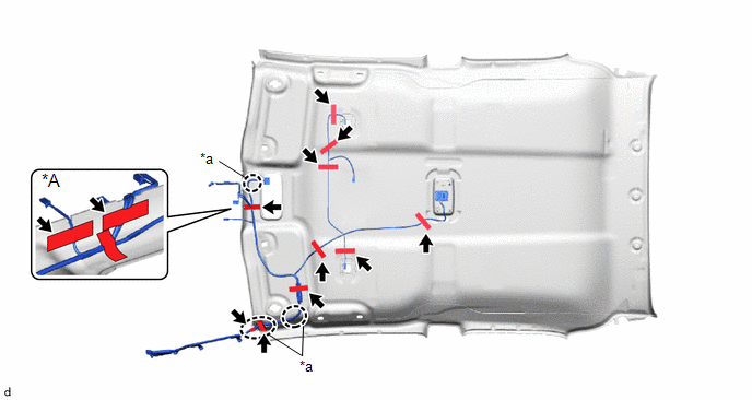
| *A | w/ Pre-collision System | - | - |
| *a | Adjustment Area | - | - |
NOTICE:
- Apply the tape securely in place.
- Do not touch the adhesive surface when applying the tape to prevent adhesion failure.
HINT:
Adjust the slack of the No. 1 roof wire as shown in the adjustment area of illustration.
3. INSTALL NO. 3 ROOF SILENCER PAD
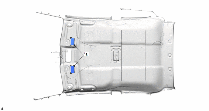
(a) Align the markings on the roof headlining with the No. 3 roof silencer pad to install them using hot melt glue as shown in the illustration.
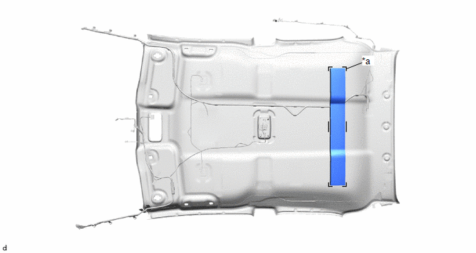
| *a | Marking | - | - |
4. INSTALL NO. 2 ROOF SILENCER PAD
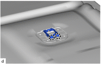
(a) Align the markings on the roof headlining with the No. 2 roof silencer pad to install them using hot melt glue as shown in the illustration.
| *a | Marking | - | - |
5. INSTALL NO. 1 ROOF SILENCER PAD
(a) Align the markings on the roof headlining with the No. 1 roof silencer pad to install them using hot melt glue as shown in the illustration.
| *a | Marking | - | - |
6. INSTALL NO. 4 ROOF SILENCER PAD
(a) Align the markings on the roof headlining with the 2 No. 4 roof silencer pads to install them using hot melt glue as shown in the illustration.
| *a | Marking | - | - |
7. INSTALL ROOF HEADLINING HOLDER COVER (w/ Active Noise Control System)
HINT:
Use the same procedure for the opposite side.
| (a) Engage the claws to install the roof headlining holder cover. |
|
8. INSTALL ACTIVE NOISE CONTROL MICROPHONE (w/ Active Noise Control System)
Click here

 Disassembly
DISASSEMBLY PROCEDURE 1. REMOVE ACTIVE NOISE CONTROL MICROPHONE (w/ Active Noise Control System) Click here
2. REMOVE ROOF HEADLINING HOLDER COVER (w/ Active Noise Control System) HINT: Use the same procedure for the opposite side...
 Installation
INSTALLATION PROCEDURE 1. INSTALL ROOF HEADLINING (a) Tilt the roof headlining diagonally and insert it into the cabin through the passenger side door as shown in the illustration...
Other information:
Toyota Yaris XP210 (2020-2026) Reapir and Service Manual: System Description
SYSTEM DESCRIPTION FUNCTION OF SRS CONNECTORS (a) Location of activation prevention mechanism (b) Function of activation prevention mechanism (1) This mechanism is designed to create a short circuit automatically between the positive (+) and negative (-) terminals of a squib power source connector when disconnected...
Toyota Yaris XP210 (2020-2026) Reapir and Service Manual: Diagnostic Trouble Code Chart
D..
Categories
- Manuals Home
- Toyota Yaris Owners Manual
- Toyota Yaris Service Manual
- How to use USB mode
- G16e-gts (engine Mechanical)
- Fuel Gauge
- New on site
- Most important about car
Front Seat Belt Pretensioners
The front seat belt pretensioners are designed to deploy in moderate or severe frontal, near frontal collisions.
In addition, the pretensioners operate when a side collision or a rollover accident is detected. The pretensioners operate differently depending on what types of air bags are equipped. For more details about the seat belt pretensioner operation, refer to the SRS Air Bag Deployment Criteria.