Toyota Yaris: Headlight Dimmer Switch / Inspection
INSPECTION
PROCEDURE
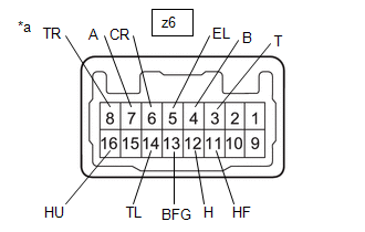
1. INSPECT TURN SIGNAL SWITCH
(a) Check the resistance.
| (1) Measure the resistance according to the value(s) in the table below. Standard Resistance: Light Control Switch | Tester Connection | Condition | Specified Condition | | z6-7 (A) - z6-5 (EL) | Light control switch in AUTO position | Below 1 Ω | | z6-3 (T) - z6-5 (EL) | Light control switch in tail position | Below 1 Ω | | z6-12 (H) - z6-5 (EL) | Light control switch in head position | Below 1 Ω | Dimmer Passing Switch | Tester Connection | Condition | Specified Condition | | z6-11 (HF) - z6-5 (EL) | Dimmer switch in high flash position | Below 1 Ω | | z6-16 (HU) - z6-5 (EL) | Dimmer switch in high position | Below 1 Ω | Fog Light Switch | Tester Connection | Condition | Specified Condition | | z6-4 (B) - z6-5 (EL) | Fog light switch in rear position | Below 1 Ω | | z6-13 (BFG) - z6-5 (EL) | Fog light switch in front position | Below 1 Ω | Turn Signal Switch | Tester Connection | Condition | Specified Condition | | z6-8 (TR) - z6-5 (EL) | Turn signal switch in neutral position | 10 kΩ or higher | | z6-14 (TL) - z6-5 (EL) | Turn signal switch in neutral position | 10 kΩ or higher | | z6-8 (TR) - z6-5 (EL) | Turn signal switch in right turn position | Below 1 Ω | | z6-8 (TR) - z6-5 (EL) | Turn signal switch in full right turn position | Below 1 Ω | | z6-8 (TR) - z6-6 (CR) | Turn signal switch in full right turn position | Below 1 Ω | | z6-6 (CR) - z6-5 (EL) | Turn signal switch in full right turn position | Below 1 Ω | | z6-14 (TL) - z6-5 (EL) | Turn signal switch in left turn position | Below 1 Ω | | z6-14 (TL) - z6-5 (EL) | Turn signal switch in full left turn position | Below 1 Ω | | z6-14 (TL) - z6-6 (CR) | Turn signal switch in full left turn position | Below 1 Ω | | z6-6 (CR) - z6-5 (EL) | Turn signal switch in full left turn position | Below 1 Ω | If the result is not as specified, replace the turn signal switch. HINT: -
The left turn or right turn condition indicates a condition in which the turn signal switch will return to the neutral position after releasing your hand from the turn signal switch (turn signal switch is operated approximately 6.3°).
-
The full left turn or full right turn condition indicates a condition in which the turn signal switch will not return to the neutral position after releasing your hand from the turn signal switch (turn signal switch is operated 10.5°).
|
| | *a | Component without harness connected (Turn Signal Switch) | | |
REMOVAL PROCEDURE 1. REMOVE LOWER STEERING COLUMN COVER Click here
2. REMOVE UPPER STEERING COLUMN COVER Click here
3. REMOVE TURN SIGNAL SWITCH (a) Remove the 2 screws...
INSTALLATION PROCEDURE 1. INSTALL TURN SIGNAL SWITCH (a) Engage the claw to install the turn signal switch as shown in the illustration.
Install in this Direction (b) Install the 2 screws...
Other information:
TERMINALS OF ECU TERMINALS OF ECU
*a Component without harness connected (Skid Control ECU [Brake Actuator Assembly]) - - Terminal No. (Symbol) Terminal Description 1 (GND2) Pump motor ground 2 - (Not used) 3 - (Not used) 4 - (Not used) 5 (STP2) Stop light switch assembly input 6 - (Not used) 7 - (Not used) 8 - (Not used) 9 - (Not used) 10 (CANL) CAN communication line L 11 - (Not used) 12 (IGR) ECU power supply input 13 (BM) Motor relay power supply 14 (SP1) Speed signal output for speedometer 15 (RR-) Rear wheel speed RH (-) signal input 16 (RR+) Rear wheel speed RH (+) power supply output 17 (FL-) Front wheel speed LH (-) signal input 18 (FL+) Front wheel speed LH (+) power supply output 19 - (Not used) 20 - (Not used) 21 - (Not used) 22 (CANH) CAN communication line H 23 - (Not used) 24 - (Not used) 25 (GND1) Skid control ECU (brake actuator assembly) ground 26 (STPO) Stop light switch assembly output 27 - (Not used) 28 (RL-) Rear wheel speed LH (-) signal input 29 (RL+) Rear wheel speed LH (+) power supply output 30 (FR-) Front wheel speed RH (-) signal input 31 (FR+) Front wheel speed RH (+) power supply output 32 - (Not used) 33 (CSW) VSC OFF switch (combination switch assembly) input 34 - (Not used) 35 (STP) Stop light switch assembly input 36 (CA2H) CAN communication line H 37 (CA2L) CAN communication line L 38 (+BS) Solenoid relay power supply TERMINAL INSPECTION (a) Disconnect the A108 connector and measure the voltage or resistance on the wire harness side...
The driver’s air bag is mounted in the steering wheel.
When air bag crash sensors
detect a frontal impact of
greater than moderate force,
the driver’s air bag inflates
quickly helping to reduce injury
mainly to the driver’s head or
chest caused by directly hitting
the steering wheel...
Categories
WARNING
When removing the fuel-filler cap, loosen the cap slightly and wait
for
any hissing to stop, then remove it
Fuel spray is dangerous. Fuel can burn skin and eyes and cause illness
if
ingested. Fuel spray is released when there is pressure in the fuel tank and
the fuel-filler cap is removed too quickly.
read more