Toyota Yaris: Horn / Horn
Components
COMPONENTS
ILLUSTRATION
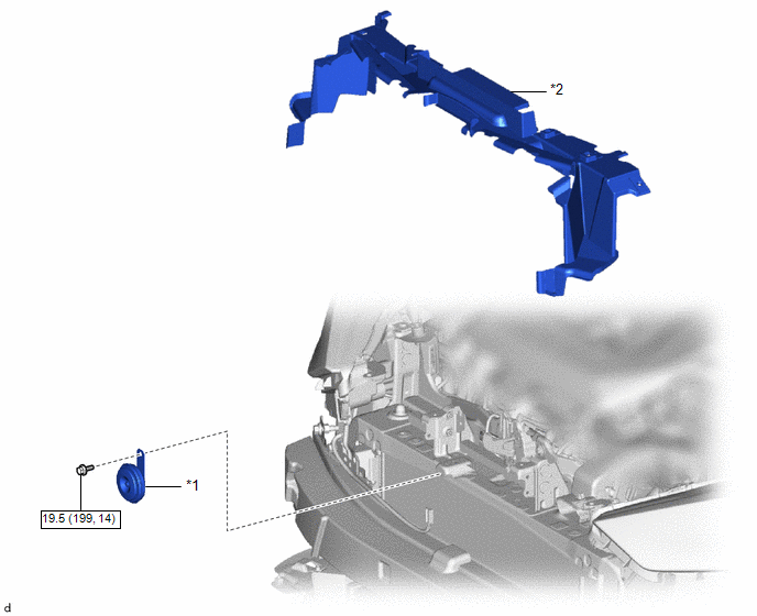
| *1 | LOW PITCHED HORN ASSEMBLY | *2 | RADIATOR UPPER AIR GUIDE PLATE |
.png) | N*m (kgf*cm, ft.*lbf): Specified torque | - | - |
Removal
REMOVAL
PROCEDURE
1. REMOVE FRONT BUMPER ASSEMBLY
Click here
.gif)
2. REMOVE RADIATOR UPPER AIR GUIDE PLATE
Click here
3. REMOVE LOW PITCHED HORN ASSEMBLY
| (a) Disconnect the connector. |
|
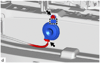
(b) Remove the bolt.
(c) Disengage the guide to remove the low pitched horn assembly.
Inspection
INSPECTION
PROCEDURE
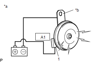
1. INSPECT LOW PITCHED HORN ASSEMBLY
(a) Check the operation.
| (1) Apply auxiliary battery voltage and check the operation of the low pitched horn assembly according to the table below. OK:
If the result is not as specified, replace the low pitched horn assembly. |
|
Installation
INSTALLATION
PROCEDURE
1. INSTALL LOW PITCHED HORN ASSEMBLY
| (a) Engage the guide to install the low pitched horn assembly. |
|
.png)
(b) Install the bolt.
Torque:
19.5 N·m {199 kgf·cm, 14 ft·lbf}
(c) Connect the connector.
2. INSTALL RADIATOR UPPER AIR GUIDE PLATE
Click here
.gif)
3. INSTALL FRONT BUMPER ASSEMBLY
Click here
 Horn
Horn
..
 Horn System
Parts LocationPARTS LOCATION ILLUSTRATION
*1 LOW PITCHED HORN ASSEMBLY *2 NO. 1 ENGINE ROOM RELAY BLOCK AND NO. 1 JUNCTION BLOCK ASSEMBLY - HORN RELAY - HORN FUSE ILLUSTRATION
*1 HORN BUTTON ASSEMBLY *2 SPIRAL CABLE SUB-ASSEMBLY *3 MAIN BODY ECU (MULTIPLEX NETWORK BODY ECU) *4 POWER DISTRIBUTION BOX ASSEMBLY *5 DLC3 - - System DiagramSYSTEM DIAGRAM
Problem Symptoms TablePROBLEM SYMPTOMS TABLE NOTICE: If the main body ECU (multiplex network body ECU) is replaced, refer to the Registration...
Other information:
Toyota Yaris XP210 (2020-2026) Reapir and Service Manual: No Answer-Back
DESCRIPTION In some cases, wireless door lock control functions are normal but the hazard warning light do not operate. In such cases, hazard warning light outputs from the main body ECU (multiplex network body ECU) may be malfunctioning. WIRING DIAGRAM CAUTION / NOTICE / HINT NOTICE: The wireless door lock control system uses the CAN communication system...
Toyota Yaris XP210 (2020-2026) Reapir and Service Manual: Ambient Temperature Sensor Circuit Short to Ground (P007011)
DESCRIPTION The thermistor assembly is installed in front of the cooler condenser assembly to detect the ambient temperature, which is used to control the air conditioning system. This sensor is connected to the combination meter assembly and detects fluctuations in the ambient temperature...
Categories
- Manuals Home
- Toyota Yaris Owners Manual
- Toyota Yaris Service Manual
- Auto Lock/Unlock Function
- Headlights
- Removal
- New on site
- Most important about car
Liftgate/Trunk Lid
WARNING
Never allow a person to ride in the luggage compartment/trunk
Allowing a person to ride in the luggage compartment/trunk is dangerous. The person in the luggage compartment/trunk could be seriously injured or killed during sudden braking or a collision.
Do not drive with the liftgate/trunk lid open