Toyota Yaris: Network Gateway Ecu / Installation
INSTALLATION
CAUTION / NOTICE / HINT
NOTICE:
After performing the update ECU security key procedure, make sure to perform the initialization procedure for when the cable has been disconnected and reconnected to the negative (-) auxiliary battery terminal.
PROCEDURE
1. INSTALL CENTRAL GATEWAY ECU (NETWORK GATEWAY ECU)
(a) Engage the claws to install the central gateway ECU (network gateway ECU) as shown in the illustration.
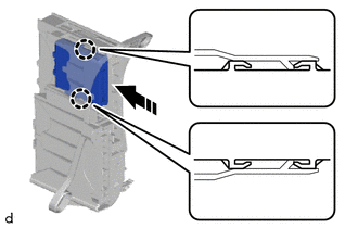
 | Install in this Direction |
NOTICE:
Make sure that the central gateway ECU (network gateway ECU) is securely installed.
2. INSTALL ECU INTEGRATION BOX RH
| (a) Engage the claws to install the ECU integration box RH. |
|
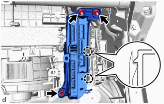
(b) Install the bolt and 2 nuts.
Torque:
8.0 N·m {82 kgf·cm, 71 in·lbf}
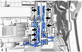
| (c) Connect the 7 connectors and engage the clamps. |
|
3. INSTALL LOWER NO. 2 INSTRUMENT PANEL FINISH PANEL
Click here

4. INSTALL GLOVE COMPARTMENT DOOR ASSEMBLY
Click here

5. INSTALL NO. 1 INSTRUMENT SIDE PANEL
Click here

6. CONNECT FRONT DOOR OPENING TRIM WEATHERSTRIP RH
HINT:
Use the same procedure as for the LH side.
Click here

7. INSTALL NO. 2 INSTRUMENT PANEL UNDER COVER SUB-ASSEMBLY
Click here

8. INSTALL COWL SIDE TRIM BOARD RH
HINT:
Use the same procedure as for the LH side.
Click here

9. INSTALL FRONT DOOR SCUFF PLATE RH
HINT:
Use the same procedure as for the LH side.
Click here

10. INSTALL CONSOLE BOX ASSEMBLY
Click here

11. INSTALL SHIFT LEVER KNOB SUB-ASSEMBLY
Click here

12. INSTALL SWITCH HOLE BASE SUB-ASSEMBLY
Click here

13. INSTALL LOWER INSTRUMENT PANEL FINISH PANEL
Click here

14. INSTALL CENTER LOWER INSTRUMENT COVER
Click here

15. CONNECT CABLE TO NEGATIVE AUXILIARY BATTERY TERMINAL
Click here

16. UPDATE ECU SECURITY KEY
Click here

17. INITIALIZATION AFTER RECONNECTING AUXILIARY BATTERY TERMINAL
HINT:
When disconnecting and reconnecting the auxiliary battery, there is an automatic learning function that completes learning when the respective system is used.
Click here

 Removal
REMOVAL CAUTION / NOTICE / HINT The necessary procedures (adjustment, calibration, initialization, or registration) that must be performed after parts are removed and installed, or replaced during the central gateway ECU (network gateway ECU) removal/installation are shown below...

Other information:
Toyota Yaris XP210 (2020-2026) Reapir and Service Manual: Terminals Of Ecu
TERMINALS OF ECU *1 Power Distribution Box Assembly *2 Main Body ECU (Multiplex Network Body ECU) CHECK MAIN BODY ECU (MULTIPLEX NETWORK BODY ECU) AND POWER DISTRIBUTION BOX ASSEMBLY (a) Remove the main body ECU (multiplex network body ECU) from the power distribution box assembly...
Toyota Yaris XP210 (2020-2026) Owner's Manual: Height Adjustment
Adjust the head restraint so that the center is even with the top of the passenger’s ears. To raise a head restraint, pull it up to the desired position. To lower the head restraint, press the stop-catch release, then push the head restraint down...
Categories
- Manuals Home
- Toyota Yaris Owners Manual
- Toyota Yaris Service Manual
- G16e-gts (engine Mechanical)
- How to use USB mode
- Auto Lock/Unlock Function
- New on site
- Most important about car
Turning the Engine Off
Stop the vehicle completely. Manual transaxle: Shift into neutral and set the parking brake.Automatic transaxle: Shift the selector lever to the P position and set the parking brake.
Press the push button start to turn off the engine. The ignition position is off.