Toyota Yaris: Blower Unit / Disassembly
DISASSEMBLY
PROCEDURE
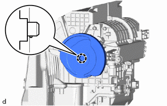
1. REMOVE NO. 1 DAMPER PLATE
| (a) Disengage the claw to remove the No. 1 damper plate. |
|
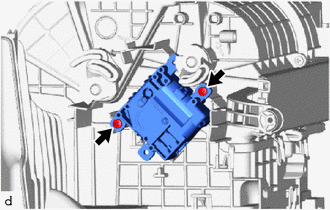
2. INSTALL NO. 1 BLOWER DAMPER SERVO SUB-ASSEMBLY
| (a) Remove the 2 screws and No. 1 blower damper servo sub-assembly. |
|
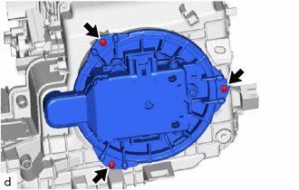
3. REMOVE BLOWER MOTOR WITH FAN SUB-ASSEMBLY
| (a) Remove the 3 screws and blower motor with fan sub-assembly. |
|
4. REMOVE AIR FILTER COVER PLATE
| (a) Disengage the claw and guides to remove the air filter cover plate. |
|
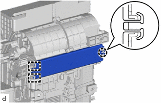
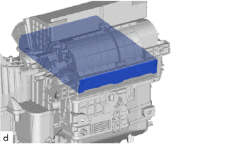
5. REMOVE CLEAN AIR FILTER
| (a) Remove the air filter sub-assembly. |
|
 Removal
REMOVAL CAUTION / NOTICE / HINT The necessary procedures (adjustment, calibration, initialization, or registration) that must be performed after parts are removed, installed, or replaced during the blower unit removal/installation are shown below...
 Reassembly
REASSEMBLY PROCEDURE 1. INSTALL CLEAN AIR FILTER (a) Install the clean air filter. NOTICE: Make sure that the "UP" mark is facing the correct direction before installing the clean air filter...
Other information:
Toyota Yaris XP210 (2020-2026) Reapir and Service Manual: Failure to Restart from IG-ON Engine Stall
DESCRIPTION This is the troubleshooting procedure for situations where the engine does not restart when attempting to restart it after either a failed engine start occurred under stop and start system control, or a mis-operation during vehicle takeoff resulted in an engine stall...
Toyota Yaris XP210 (2020-2026) Reapir and Service Manual: Components
COMPONENTS ILLUSTRATION *1 NO. 1 AIR CLEANER INLET *2 RADIATOR UPPER AIR GUIDE PLATE *3 FRONT BUMPER ENERGY ABSORBER *4 FRONT BUMPER REINFORCEMENT *5 HOOD LOCK ASSEMBLY *6 UPPER RADIATOR SUPPORT SUB-ASSEMBLY N*m (kgf*cm, ft...
Categories
- Manuals Home
- Toyota Yaris Owners Manual
- Toyota Yaris Service Manual
- Maintenance
- Immobilizer System
- Engine & Hybrid System
- New on site
- Most important about car
Fuel Gauge
The fuel gauge shows approximately how much fuel is remaining in the tank when the ignition is switched ON. We recommend keeping the tank over 1/4 full.

Copyright © 2026 www.toyaris4.com