
Toyota Yaris: Knock Sensor / Inspection
INSPECTION
PROCEDURE
1. INSPECT KNOCK SENSOR
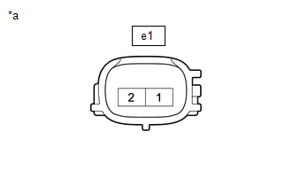
| (a) Measure the resistance according to the value(s) in the table below. Standard Resistance:
If the result is not as specified, replace the knock sensor. |
|
 Removal
REMOVAL CAUTION / NOTICE / HINT The necessary procedures (adjustment, calibration, initialization, or registration) that must be performed after parts are removed, installed, or replaced during the knock sensor removal/installation are shown below...
 Installation
INSTALLATION CAUTION / NOTICE / HINT NOTICE: This procedure includes the installation of small-head bolts. Refer to Small-Head Bolts of Basic Repair Hint to identify the small-head bolts...
Other information:
Toyota Yaris XP210 (2020-2026) Reapir and Service Manual: Inspection
INSPECTION PROCEDURE 1. INSPECTION AFTER COLLISION (a) Inspect the SRS parts in table below. CAUTION: Be sure to read Precaution thoroughly before servicing. Click here Be sure to correctly follow the removal and installation procedures for the SRS parts...
Toyota Yaris XP210 (2020-2026) Reapir and Service Manual: Terminals Of Ecu
TERMINALS OF ECU CHECK MULTIPLEX NETWORK MASTER SWITCH ASSEMBLY (a) Disconnect the L13 multiplex network master switch assembly connector. (b) Measure the voltage and resistance according to the value(s) in the table below. HINT: Measure the values on the wire harness side with the connector disconnected...
Categories
- Manuals Home
- Toyota Yaris Owners Manual
- Toyota Yaris Service Manual
- Fuse Panel Description
- How to connect USB port/Auxiliary jack
- Fuel Gauge
- New on site
- Most important about car
Turning the Engine Off
Stop the vehicle completely. Manual transaxle: Shift into neutral and set the parking brake.Automatic transaxle: Shift the selector lever to the P position and set the parking brake.
Press the push button start to turn off the engine. The ignition position is off.
Copyright © 2026 www.toyaris4.com