Toyota Yaris: Knock Sensor / Removal
REMOVAL
CAUTION / NOTICE / HINT
The necessary procedures (adjustment, calibration, initialization, or registration) that must be performed after parts are removed, installed, or replaced during the knock sensor removal/installation are shown below.
Necessary Procedure After Parts Removed/Installed/Replaced| Replacement Part or Procedure | Necessary Procedure | Effect/Inoperative when not Performed | Link |
|---|---|---|---|
| Inspection after repair |
|
|

CAUTION / NOTICE / HINT
PROCEDURE
1. REMOVE INTAKE MANIFOLD
Click here

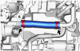
2. REMOVE NO. 4 WATER BY-PASS HOSE
| (a) Slide the 2 clips and remove the No. 4 water by-pass hose. |
|
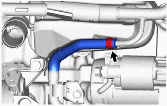
3. DISCONNECT NO. 6 WATER BY-PASS HOSE
| (a) Slide the clip and disconnect the No. 6 water by-pass hose. |
|
4. SEPARATE NO. 2 WATER BY-PASS PIPE
Click here

5. REMOVE NO. 2 CYLINDER BLOCK INSULATOR
Click here

6. REMOVE NO. 1 VENTILATION CASE
Click here

7. REMOVE KNOCK SENSOR
| (a) Disconnect the knock sensor connector. |
|
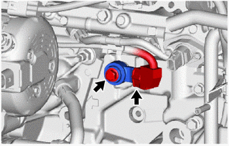
(b) Remove the bolt and knock sensor from the cylinder block sub-assembly.
NOTICE:
If the knock sensor has been struck or dropped, replace it.
 Components
COMPONENTS ILLUSTRATION
*1 KNOCK SENSOR *2 NO. 1 VENTILATION CASE *3 NO. 2 CYLINDER BLOCK INSULATOR *4 NO. 2 WATER BY-PASS PIPE *5 NO...
 Inspection
INSPECTION PROCEDURE 1. INSPECT KNOCK SENSOR (a) Measure the resistance according to the value(s) in the table below. Standard Resistance: Tester Connection Condition Specified Condition e1-1 - e1-2 25°C (77°F) 120 to 280 kΩ If the result is not as specified, replace the knock sensor...
Other information:
Toyota Yaris XP210 (2020-2026) Reapir and Service Manual: Components
COMPONENTS ILLUSTRATION *1 NO. 1 ENGINE UNDER COVER ASSEMBLY *2 SUCTION HOSE SUB-ASSEMBLY *3 NO. 1 COOLER REFRIGERANT DISCHARGE HOSE *4 COMPRESSOR WITH PULLEY ASSEMBLY *5 O-ring - - Tightening torque for "Major areas involving basic vehicle performance such as moving/turning/stopping" : N*m (kgf*cm, ft...
Toyota Yaris XP210 (2020-2026) Reapir and Service Manual: How To Proceed With Troubleshooting
CAUTION / NOTICE / HINT HINT: Replace parts related to the wireless door lock and smart key system according to the inspection procedure. If the wireless door lock and smart key system does not operate, first check the customize item and make sure that the wireless door lock and smart key system is not turned off...
Categories
- Manuals Home
- Toyota Yaris Owners Manual
- Toyota Yaris Service Manual
- Auto Lock/Unlock Function
- Fuse Panel Description
- Diagnostic Trouble Code Chart
- New on site
- Most important about car
Supplemental Restraint System (SRS) Precautions
The front and side supplemental restraint systems (SRS) include different types of air bags. Please verify the different types of air bags which are equipped on your vehicle by locating the “SRS AIRBAG” location indicators. These indicators are visible in the area where the air bags are installed.
The air bags are installed in the following locations:
The steering wheel hub (driver air bag) The front passenger dashboard (front passenger air bag) The outboard sides of the front seatbacks (side air bags) The front and rear window pillars, and the roof edge along both sides (curtain air bags)