Toyota Yaris: Knock Sensor / Components
COMPONENTS
ILLUSTRATION
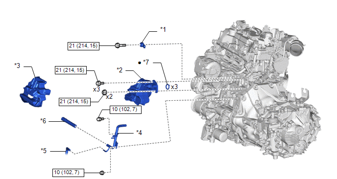
| *1 | KNOCK SENSOR | *2 | NO. 1 VENTILATION CASE |
| *3 | NO. 2 CYLINDER BLOCK INSULATOR | *4 | NO. 2 WATER BY-PASS PIPE |
| *5 | NO. 6 WATER BY-PASS HOSE | *6 | NO. 4 WATER BY-PASS HOSE |
| *7 | GASKET | - | - |
 | N*m (kgf*cm, ft.*lbf): Specified torque | ● | Non-reusable part |
 Knock Sensor
..
 Removal
REMOVAL CAUTION / NOTICE / HINT The necessary procedures (adjustment, calibration, initialization, or registration) that must be performed after parts are removed, installed, or replaced during the knock sensor removal/installation are shown below...
Other information:
Toyota Yaris XP210 (2020-2026) Owner's Manual: Rear View Parking Camera Location
4-Door 5-Door Switching to the Rear View Monitor Display Shift the shift lever to R with the ignition switched ON to switch the display to the rear view monitor display. When the shift lever is shifted from R to another shift lever position, the screen returns to the previous display...
Toyota Yaris XP210 (2020-2026) Reapir and Service Manual: Inspection
INSPECTION PROCEDURE 1. INSPECT NO. 1 OUTPUT SHAFT (a) Check the No. 1 output shaft for wear and damage. (b) Using a dial indicator, check the No. 1 output shaft runout. Maximum Runout: 0.01 mm (0.000394 in.) (1) If the runout exceeds the maximum, replace the No...
Categories
- Manuals Home
- Toyota Yaris Owners Manual
- Toyota Yaris Service Manual
- Battery Monitor Module General Electrical Failure (P058A01)
- Brake System Control Module "A" System Voltage System Voltage Low (C137BA2)
- Immobilizer System
- New on site
- Most important about car
Break-In Period
No special break-in is necessary, but a few precautions in the first 600 miles (1,000 km) may add to the performance, economy, and life of the vehicle.
Do not race the engine. Do not maintain one constant speed, either slow or fast, for a long period of time. Do not drive constantly at full-throttle or high engine rpm for extended periods of time. Avoid unnecessary hard stops. Avoid full-throttle starts.
Copyright © 2026 www.toyaris4.com