Toyota Yaris: Cylinder Head / Disassembly
DISASSEMBLY
CAUTION / NOTICE / HINT
The necessary procedures (adjustment, calibration, initialization, or registration) that must be performed after parts are removed and installed, or replaced during cylinder head removal/installation are shown below.
Necessary Procedure After Parts Removed/Installed/Replaced| Replaced Part or Performed Procedure | Necessary Procedure | Effect/Inoperative Function when Necessary Procedure not Performed | Link |
|---|---|---|---|
| Cylinder head sub-assembly | Inspection after repair |
|
|

PROCEDURE
1. REMOVE INTAKE VALVE
| (a) Using SST, compress each compression spring and remove the 6 valve spring retainer locks. SST: 09202-70020 09202-01010 09202-01020 SST: 09202-00021 HINT: Arrange the removed parts in such a way that they can be reinstalled to their original locations. |
|
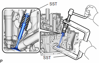
(b) Remove the 6 valve spring retainers, 6 compression springs and 6 intake valves from the cylinder head sub-assembly.
HINT:
Arrange the removed parts in such a way that they can be reinstalled to their original locations.
2. REMOVE EXHAUST VALVE
CAUTION:
- The exhaust valve is filled with sodium. Sodium is a strong alkali which may produce a dangerous chemical reaction. Therefore, be very careful when handling and disposing of it.
- Do not disassemble the exhaust valve for the following reasons: 1) If sodium enters your eyes, vision loss may occur. 2) If sodium contacts your skin, burns may occur. 3) If sodium is exposed to a flame and starts a fire due to the chemical reaction that takes place, burns may occur.
- If the exhaust valve is damaged, remove the valve and perform the proper procedures to dispose of the sodium (disposal preparation and actual disposal).
- When removing a damaged exhaust valve, always wear rubber gloves and safety glasses.
- Do not cut the exhaust valve to take out the sodium.
HINT:
- The sodium inside the exhaust valve is safe as long as the sodium is not exposed to air.
- Exhaust valves filled with sodium can be identified by confirming the "NA" identification mark.
| (a) Using SST, compress each compression spring and remove the 6 valve spring retainer locks. SST: 09202-70020 09202-01010 09202-01020 SST: 09202-00021 HINT: Arrange the removed parts in such a way that they can be reinstalled to their original locations. |
|
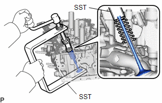
(b) Remove the 6 valve spring retainers, 6 compression springs and 6 exhaust valves from the cylinder head sub-assembly.
HINT:
Arrange the removed parts in such a way that they can be reinstalled to their original locations.
3. REMOVE VALVE STEM OIL SEAL
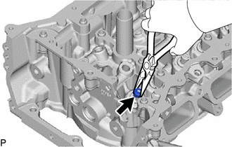
| (a) Using needle-nose pliers, remove the 12 valve stem oil seals. |
|
4. REMOVE VALVE SPRING SEAT
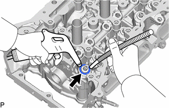
| (a) Using compressed air and a Magnet Hand, remove the 12 valve spring seats from the cylinder head sub-assembly by blowing air onto them. |
|
5. REMOVE NO. 1 STRAIGHT SCREW PLUG
NOTICE:
If coolant leaks from a No. 1 straight screw plug or a plug is corroded, replace it.
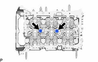
(a) Using a 6 mm straight hexagon wrench, remove the 2 No. 1 straight screw plugs from the cylinder head sub-assembly.
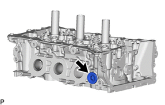
6. REMOVE NO. 2 STRAIGHT SCREW PLUG
NOTICE:
If coolant leaks from a No. 2 straight screw plug or a plug is corroded, replace it.
| (a) Using a 10 mm straight hexagon wrench, remove the No. 2 straight screw plug from the cylinder head sub-assembly. |
|
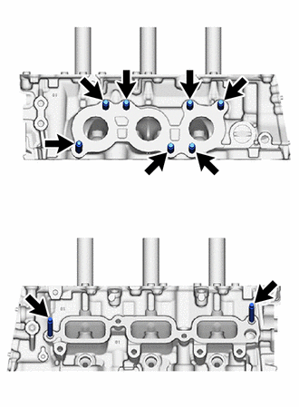
7. REMOVE STUD BOLT
NOTICE:
If a stud bolt is deformed or its threads are damaged, replace it.
| (a) Using an E8 "TORX" socket wrench, remove the 9 stud bolts. |
|
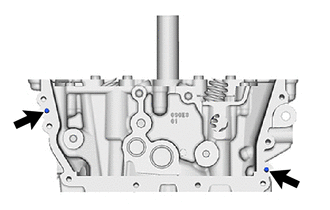
8. REMOVE STRAIGHT PIN
NOTICE:
If a straight pin is deformed or its threads are damaged, replace it.
| (a) Remove the 2 straight pin. |
|
9. DISPOSE OF EXHAUST VALVE
CAUTION:
- The exhaust valve is filled with sodium. Sodium is a strong alkali which may produce a dangerous chemical reaction. Therefore, be very careful when handling and disposing of it.
- Do not disassemble the exhaust valve for the following reasons: 1) If sodium enters your eyes, vision loss may occur. 2) If sodium contacts your skin, burns may occur. 3) If sodium is exposed to a flame and starts a fire due to the chemical reaction that takes place, burns may occur.
- If the exhaust valve is damaged, remove the valve and perform the proper procedures to dispose of the sodium (disposal preparation and actual disposal).
- When removing a damaged exhaust valve, always wear rubber gloves and safety glasses.
- Do not cut the exhaust valve to take out the sodium.
NOTICE:
If it is clearly stated that the industrial waste disposal method is dissolution, carry out the process below.
HINT:
- The sodium inside the exhaust valve is safe as long as the sodium is not exposed to air.
- Exhaust valves filled with sodium can be identified by confirming the "NA" identification mark.
(a) Waste disposal preparation
CAUTION:
Always carry out the following when performing the disposal procedure.
(1) Have a fire extinguisher close by.
(2) Wear safety glasses.
(3) Wear rubber gloves.
(b) Waste disposal
(1) Put on rubber gloves and remove the damaged exhaust valve from the cylinder head.
(2) Add 10 L of water or more to a large receptacle (a bucket, oil can, etc.) in a well-ventilated area.
(3) Hold the damaged exhaust valve upright with pliers or large pair of tweezers and submerge it into the water.
CAUTION:
- Fully submerge the damaged exhaust valve in water.
- Do not allow any sparks or other flames near the receptacle as hydrogen gas is generated by the chemical reaction.
- Stay 2 or 3 m or more away from the receptacle as a strong chemical reaction occurs.
 Components
COMPONENTS ILLUSTRATION
*1 INTAKE VALVE GUIDE BUSH *2 EXHAUST VALVE GUIDE BUSH *3 SPARK PLUG TUBE *4 RING PIN *5 STUD BOLT *6 VALVE SPRING RETAINER LOCK *7 NO...
 Inspection
INSPECTION PROCEDURE 1. INSPECT CYLINDER HEAD SUB-ASSEMBLY (a) Using a precision straightedge and feeler gauge, measure the warpage of the contact surfaces where the cylinder head sub-assembly contacts the cylinder block sub-assembly, intake manifold and exhaust manifold...
Other information:
Toyota Yaris XP210 (2020-2026) Reapir and Service Manual: Terminals Of Ecu
TERMINALS OF ECU NOTICE: After the ignition switch is turned off, there may be a waiting time before disconnecting the negative (-) auxiliary battery terminal. Click here When disconnecting and reconnecting the auxiliary battery. Click here CHECK POWER DISTRIBUTION BOX ASSEMBLY AND MAIN BODY ECU (MULTIPLEX NETWORK BODY ECU) (a) Remove the main body ECU (multiplex network body ECU) from the power distribution box assembly...
Toyota Yaris XP210 (2020-2026) Owner's Manual: Stop Vehicle in Safe Place Immediately
If any of the following warning lights turns on, the system may have a malfunction. Stop the vehicle in a safe place immediately and contact your Toyota dealer. Power Steering Malfunction Indicator Light If the indicator light illuminates/flashes, the power steering will not operate normally...
Categories
- Manuals Home
- Toyota Yaris Owners Manual
- Toyota Yaris Service Manual
- Brake System Control Module "A" System Voltage System Voltage Low (C137BA2)
- Power Integration No.1 System Missing Message (B235287,B235587,B235787-B235987)
- Immobilizer System
- New on site
- Most important about car
Fuel-Filler Lid and Cap
WARNING
When removing the fuel-filler cap, loosen the cap slightly and wait for any hissing to stop, then remove it
Fuel spray is dangerous. Fuel can burn skin and eyes and cause illness if ingested. Fuel spray is released when there is pressure in the fuel tank and the fuel-filler cap is removed too quickly.